

Tin drop detection and recovery device
A recycling device and tin drop technology, applied in the field of lithography machines, can solve the problems of tin drop emission angle deviation, affecting the efficiency of lithography machines, unable to effectively generate extreme ultraviolet radiation, etc., to achieve the effect of improving the recycling rate
- Summary
- Abstract
- Description
- Claims
- Application Information
AI Technical Summary
Problems solved by technology
Method used
Image

Examples
Embodiment 1
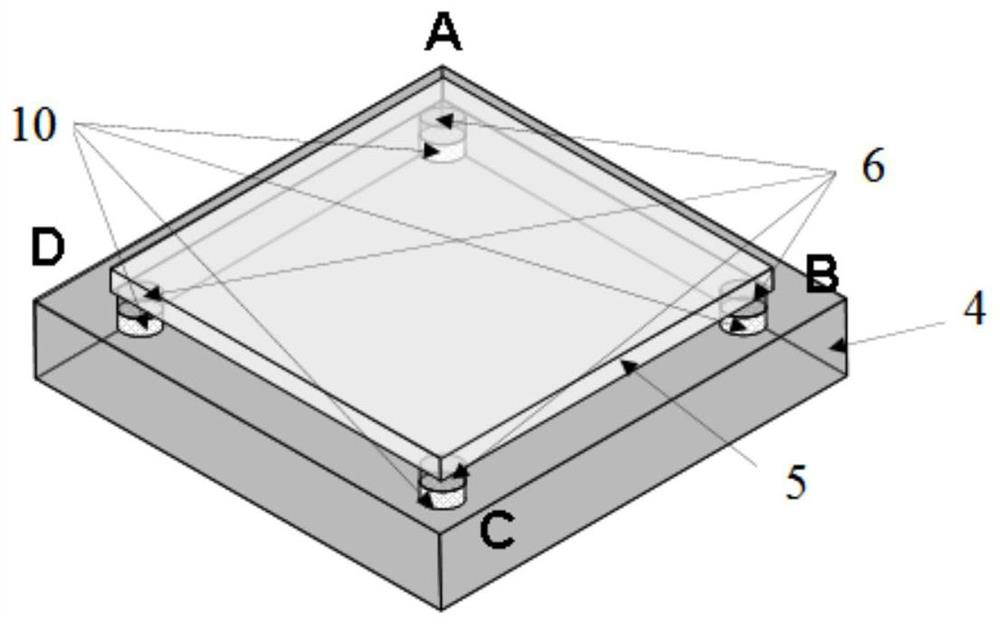
[0040] Such as Figure 4 As shown, there are four piezoelectric ceramics in the tin drop detector, and the position of the tin drop is determined by the voltage value of the piezoelectric ceramics. The piezoelectric ceramics are clamped on the four corners by extremely thin stainless steel plates and substrates. Such as Figure 4 shown. In view of the possible positions of the three kinds of tin droplets, the principle of piezoelectric ceramic detection and tin drop nozzle position adjustment is explained. The whole stainless steel plate is divided into four parts, namely A, B, C, D. The piezoelectric ceramics pass through the preamplifier The measured voltage signals are V A , V B , V C , V D :
[0041] When the tin drop is in position 1: V A 1 =V B 1 =V C 1 =V D 1 , indicating that the tin drop is exactly in the center of the square composed of four piezoelectric ceramics, so there is no need to adjust the tin drop nozzle.
[0042] When the tin drop is in posi...
PUM
 Abstract
Description
Claims
Application Information