
A kind of diode ink drying equipment

A technology for drying equipment and diodes, which is applied in lighting and heating equipment, household refrigeration equipment, semiconductor devices, etc., which can solve the problems of inconvenient processing of diodes, loss of stickiness of paper tape, and diode detachment from paper tape, etc., so as to reduce the risk of overheating and softening Probability, prevent detachment from washi tape, avoid loss of stickiness effect

Active Publication Date: 2022-04-22
CHANGZHOU ZHIDE ELECTRONICS CO LTD
View PDF12 Cites 0 Cited by
  • Summary
  • Abstract
  • Description
  • Claims
  • Application Information

AI Technical Summary

Problems solved by technology

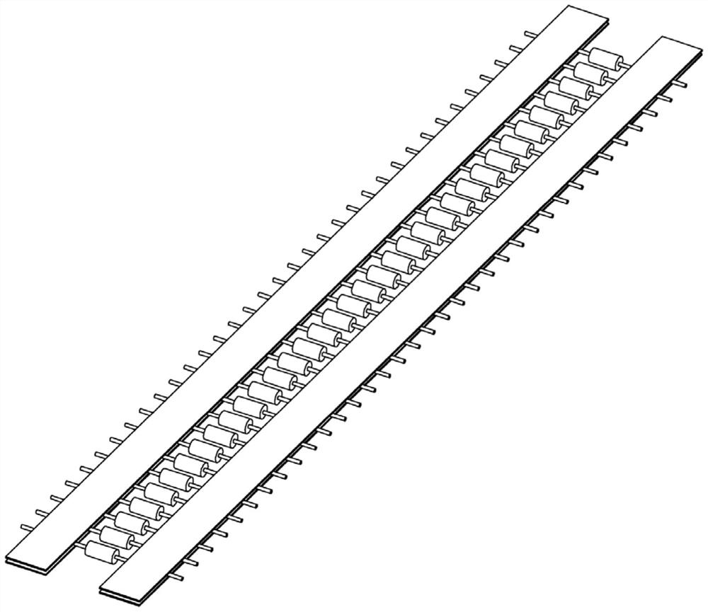
[0003] After the production of diodes is completed, it is necessary to use paper tape to pack multiple diodes into a row. The packaging effect is as shown in the attached manual. figure 1 As shown, the metal pins at both ends of the diode are bonded into a row by two layers of paper tape. This packaging method prevents the diodes from contacting each other, reduces the probability of mutual friction and damage, and is convenient for packaging and selling while also being convenient to take and use; After the diodes are packaged in a row, ink needs to be sprayed on the side of the diodes. The ink is used to record the specifications of the diodes. After the diodes are sprayed, the ink needs to be dried with a heat gun. However, the hot air blown by the heat gun will directly blow the entire row. Diode, this will make the glue on the paper tape overheat and soften, causing the paper tape to lose its viscosity, which will easily make the diode detach from the paper tape, which will cause inconvenience to the processing of the diode. To solve the above problems, we propose a diode ink drying equipment

Method used


Image

  • A kind of diode ink drying equipment
  • A kind of diode ink drying equipment
  • A kind of diode ink drying equipment

Examples


Embodiment Construction

[0037] In order to enable those skilled in the art to better understand the present invention, the technical solution of the present invention will be further described below in conjunction with the accompanying drawings and embodiments.

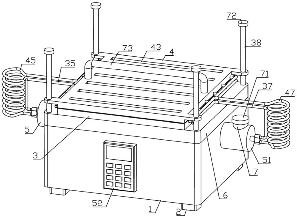
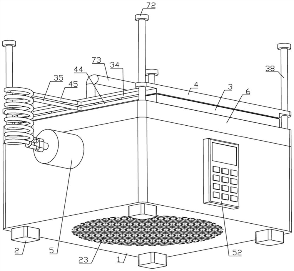
[0038] Such as Figure 2-9 As shown, a diode ink drying device of the present invention includes a box body 1, and the lower end of the box body 1 is provided with four support feet 2 distributed in a rectangular shape, and the inside of the box body 1 is fixedly connected with a fan 21 and a cooling fan 21 from bottom to top. The water tank 22 is filled with coolant inside the cooling water tank 22, the lower end of the box body 1 is provided with an air inlet hole 23 matching the fan 21, and the upper end of the box body 1 is fixedly connected with an electric heater 24;

[0039] The upper end of the electric heater 24 is fixedly connected with a lower bearing plate 3, the upper end of the lower bearing plate 3 is provided with several low...


PUM


Abstract

The invention belongs to the technical field of diode processing, and specifically relates to a diode ink drying equipment, which includes a box body, the box body is provided with a fan and a cooling water tank, the box body is provided with an electric heater, the electric heater is provided with a lower bearing plate, and the lower bearing plate The board is provided with a lower hollow copper box, the lower hollow copper box is provided with the first ventilation groove, the upper end of the electric heater is provided with a slide bar, the slide bar is provided with an upper bearing plate, the upper bearing plate is provided with an upper hollow copper box, and the upper hollow copper box There is a third ventilation groove, the upper bearing plate is equipped with a fourth ventilation groove, and the heat dissipation water tank is equipped with a water pump; the drying equipment can dry the ink on the side of the diodes in rows, and can avoid the ink on the paper tape during the drying process. The glue is overheated and softened to prevent the paper tape from losing its stickiness, so as to prevent the diode from detaching from the paper tape, thereby bringing convenience to the processing process of the diode.

Description

technical field [0001] The invention belongs to the technical field of diode processing, and in particular relates to a diode ink drying device. Background technique [0002] A diode is a device with two electrodes among electronic components that only allows current to flow in one direction. The most common function of a diode is to only allow current to pass in a single direction (called forward bias), and to block it when it is reversed (called reverse bias). So a diode can be thought of as the electronic version of a check valve. [0003] After the production of diodes is completed, it is necessary to use paper tape to pack multiple diodes into a row. The packaging effect is as shown in the attached manual. figure 1 As shown, the metal pins at both ends of the diode are bonded into a row by two layers of paper tape. This packaging method prevents the diodes from contacting each other, reduces the probability of mutual friction and damage, and is convenient for packagin...

Claims


Application Information

Patent Timeline
Patent Type & Authority Patents(China)
IPC IPC(8): B41F23/04H01L29/861F25D1/00
CPCB41F23/04H01L29/861F25D1/00
Inventor 吴国华
Owner CHANGZHOU ZHIDE ELECTRONICS CO LTD
Learn More