Multi-layer cascade diffraction vortex beam multiplexing and demultiplexing device

A vortex beam and demultiplexing technology, applied in the field of optical communication, which can solve the problems of high loss, narrow band, and small number of modes.

Inactive Publication Date: 2021-04-27
SUN YAT SEN UNIV
View PDF4 Cites 4 Cited by
  • Summary
  • Abstract
  • Description
  • Claims
  • Application Information

AI Technical Summary

Problems solved by technology

However, the above-mentioned solutions all have the problems of narrow band, high loss, high interference and small number of modes.

Method used


Image

  • Multi-layer cascade diffraction vortex beam multiplexing and demultiplexing device
  • Multi-layer cascade diffraction vortex beam multiplexing and demultiplexing device
  • Multi-layer cascade diffraction vortex beam multiplexing and demultiplexing device

Examples


Embodiment 1

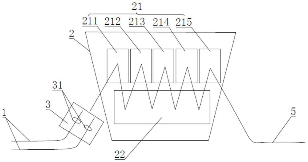
[0033] Such as Figure 1 to Figure 8 Shown is a multi-layer cascaded diffractive vortex beam multiplexing and demultiplexing device, including sequentially connected single-mode fiber array 1, multiplexing and demultiplexing system 2, vortex optical fiber 5, and multiplexing and demultiplexing system 2 Including the phase plate 21, wherein the phase plate 21 includes the first phase plate 211, the second phase plate 212, the third phase plate 213, the fourth phase plate 214, the fifth phase plate 215 arranged in sequence, the first phase plate is close to the single In the mode fiber array 1, the phase distributions of the five phase plates 21 are different.

[0034] Of course, the implementation of five phase plates 21 in this embodiment is only a reference, and it should not be understood as a limitation to this solution. Make the system performance optimal; generally, more phase plates 21 make the degree of freedom of regulation more, multiplexing and demultiplexing effect...

Embodiment 2

[0046] Such as Figure 9 Shown is a second embodiment of a multi-layer cascaded diffractive vortex beam multiplexing and demultiplexing device, which differs from the first embodiment only in that this embodiment also includes a beam shrinking and expanding system 4, the beam shrinking The beam expansion system 4 is arranged between the multiplexing and demultiplexing system 2 and the vortex optical fiber 5 .

[0047] The beam reduction and expansion system 4 in this embodiment includes a first lens 41 and a second lens 42 with different focal lengths, the focal length ratio of the first lens 41 and the second lens 42 is 20:1, wherein the first lens is close to the multiplexing solution The multiplexing system 2 , the second lens 42 is far away from the multiplexing and demultiplexing system 2 . Since the mode field size in the vortex fiber 5 is small, and the mode field size of the free-space multiplexed vortex beam is relatively large, it is necessary to constrain the multi...


PUM


Abstract

The invention belongs to the technical field of optical communication, and particularly relates to a multi-layer cascade diffraction vortex beam multiplexing and demultiplexing device, which comprises a single-mode optical fiber array, a multiplexing and demultiplexing system and a vortex optical fiber which are connected in sequence, and the multiplexing and demultiplexing system comprises a plurality of phase plates which are optimized and adjusted through a gradient descent method to obtain different phases. Phase distribution of a phase plate in the multiplexing and demultiplexing system is optimized and adjusted through a gradient descent method, so that the matching degree of output of the multiplexing and demultiplexing system and a single-mode optical fiber array or a vortex optical fiber is maximized, and therefore the maximum coupling efficiency is achieved; in addition, due to the application of the single-mode optical fiber array, the device can support multiplexing and demultiplexing of multiple vortex modes, and high-efficiency and multi-mode vortex beam multiplexing and demultiplexing are achieved.

Description

technical field [0001] The invention belongs to the technical field of optical communication, and more specifically relates to a multilayer cascaded diffractive vortex beam multiplexing and demultiplexing device. Background technique [0002] With the development of wavelength division multiplexing, amplitude control, polarization multiplexing and other technologies, the channel capacity of traditional optical fiber communication technology is gradually approaching the bottleneck. With the rise of various new technologies such as big data, cloud computing, and unmanned driving, the demand for optical communication capacity continues to increase. In order to solve the contradiction between the communication capacity demand faced in the future and the bottleneck of existing technologies, it is urgent to develop new optical communication technologies. One of the most promising solutions to this problem is to use light to perform space division multiplexing. Space division mult...

Claims


Application Information

Patent Timeline
Patent Type & Authority Applications(China)
IPC IPC(8): G02B6/28G02B6/27G02B6/32
CPCG02B6/2766G02B6/2773G02B6/2804G02B6/32
Inventor 李朝晖刘志兵邹佳慧
Owner SUN YAT SEN UNIV
Why Eureka
Try Eureka