Edge passivation method of HJT battery

A battery and edge technology, which is applied in the field of HJT batteries, can solve the problems of amorphous silicon film structure damage, severe cutting surface recombination, HJT battery efficiency loss, etc., and achieve good passivation effect, high production efficiency, and high conversion efficiency.

Pending Publication Date: 2021-04-27
ZHEJIANG AIKO SOLAR ENERGY TECH CO LTD +2
View PDF5 Cites 0 Cited by
  • Summary
  • Abstract
  • Description
  • Claims
  • Application Information

AI Technical Summary

Problems solved by technology

[0003] Before the HJT battery is prepared into components, it is usually necessary to divide the whole HJT battery by laser scribing and splitting to obtain independent HJT battery slices; laser scribing will cause certain defects on the edge of the HJT battery slice, forming a recombination center, And because the silicon substrate itself lacks the coverage of the passivation layer, the recombination of the cut surface is serious, which usually brings more than 0.3% efficiency loss to the HJT battery
[0004] However, the existing edge passivation method requires long-term deposition under high temperature conditions to form a passivation layer. High temperature conditions will cause damage to the structure of the amorphous silicon film of the HJT battery, thereby greatly reducing the passivation effect of the HJT battery. , so the existing technology cannot realize the edge passivation of HJT cells

Method used


Image

  • Edge passivation method of HJT battery
  • Edge passivation method of HJT battery
  • Edge passivation method of HJT battery

Examples


Embodiment 1

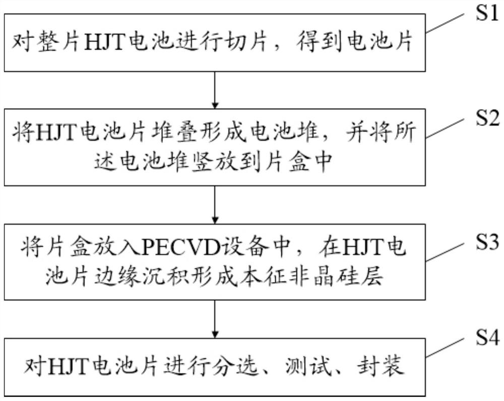
[0055] (1) Slicing the whole HJT battery to obtain HJT battery slices;

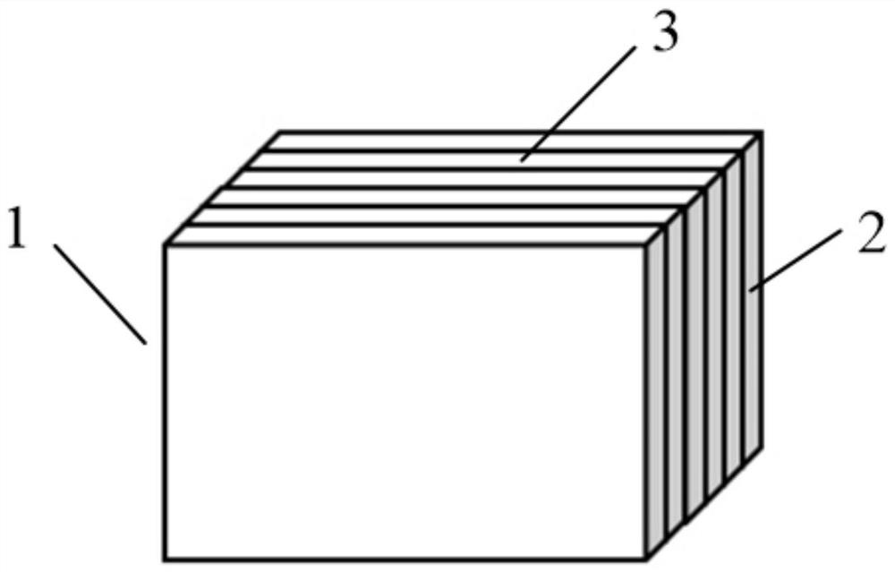
[0056] (2) Stack the HJT cells to form a cell stack, and place the cell stack vertically in the sheet box;

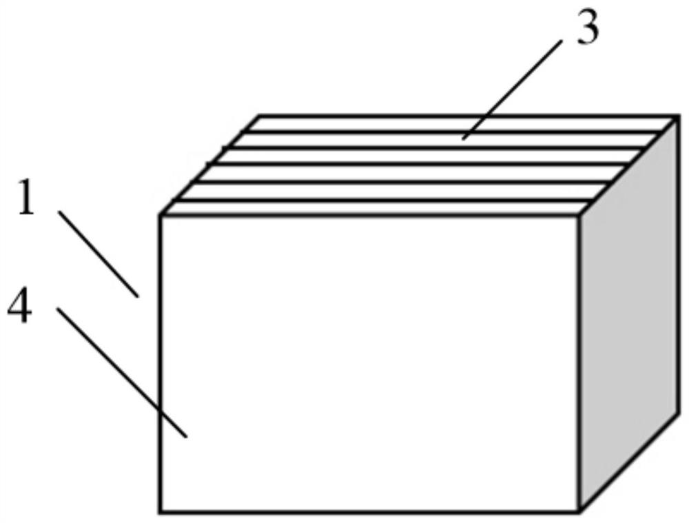
[0057] (3) Put the film cassette into the PECVD equipment, under the conditions of working power of 2000W and chamber pressure of 3Torr, feed SiH 4 and H 2 , depositing an intrinsic amorphous silicon layer on the edge of the HJT cell, the deposition temperature is 230°C, and the deposition time is 200s; the thickness of the intrinsic amorphous silicon layer is obtained to be 50nm;

[0058] (4) Sorting, testing and packaging the HJT cells.

Embodiment 2

[0060] (1) Slicing the whole HJT battery to obtain HJT battery slices;

[0061] (2) Stack the HJT cells to form a cell stack, and place the cell stack vertically in the sheet box;

[0062] (3) Put the cassette into the PECVD equipment, under the condition of working power of 800W and chamber pressure of 1Torr, feed SiH 4 and H 2 , depositing an intrinsic amorphous silicon layer on the edge of the HJT cell, the deposition temperature is 180°C, and the deposition time is 20s; the thickness of the intrinsic amorphous silicon layer is obtained to be 10nm;

[0063] (4) Sorting, testing and packaging the HJT cells.

Embodiment 3

[0065] (1) Slicing the whole HJT battery to obtain HJT battery slices;

[0066] (2) Stack the HJT cells to form a cell stack, and place the cell stack vertically in the sheet box;

[0067] (3) Put the cassette into the PECVD equipment, under the conditions of working power of 1000W and chamber pressure of 2Torr, feed SiH 4 and H 2 , depositing an intrinsic amorphous silicon layer on the edge of the HJT cell, the deposition temperature is 200°C, and the deposition time is 80s; the thickness of the intrinsic amorphous silicon layer is obtained to be 30nm;

[0068] (4) Sorting, testing and packaging the HJT cells.


PUM

PropertyMeasurementUnit
Deposition thicknessaaaaaaaaaa
Thicknessaaaaaaaaaa
Thicknessaaaaaaaaaa

Abstract

The invention discloses an edge passivation method for an HJT battery. The method comprises the following steps: (1) slicing the whole HJT battery to obtain HJT battery pieces; (2) stacking the HJT battery pieces to form a battery stack, and vertically placing the battery stack into a piece box; (3) putting the piece box into PECVD equipment, and performing depositing on the edges of the HJT battery pieces to form an intrinsic amorphous silicon layer; and (4) subjecting the HJT battery pieces to sorting, testing and packaging. In the step (3), the deposition temperature for depositing the intrinsic amorphous silicon layer is 180-230 DEG C, and the deposition time is 20-200s. The method is simple and convenient to operate and high in production efficiency, can realize edge passivation of the HJT battery, and obtains the HJT battery with good passivation effect and high conversion efficiency.

Description

technical field [0001] The invention relates to the technical field of HJT batteries, in particular to an edge passivation method of HJT batteries. Background technique [0002] HJT battery is made by depositing amorphous silicon film on crystalline silicon, which is a kind of N-type battery. The structure of HJT battery can improve the performance of PN junction, so that the conversion efficiency and open circuit voltage can be improved. [0003] Before the HJT battery is prepared into components, it is usually necessary to divide the whole HJT battery by laser scribing and splitting to obtain independent HJT battery slices; laser scribing will cause certain defects on the edge of the HJT battery slice, forming a recombination center, Moreover, due to the lack of coverage of the passivation layer on the silicon substrate itself, the recombination of the cut surface is serious, which usually brings an efficiency loss of more than 0.3% to the HJT cell. [0004] However, the ...

Claims


Application Information

Patent Timeline
IPC IPC(8): H01L31/20H01L31/18H01L31/0216H01L31/072
CPCH01L31/02167H01L31/072H01L31/1876H01L31/202H01L31/208Y02E10/50Y02P70/50
Inventor 吴智涵王永谦林纲正陈刚
Owner ZHEJIANG AIKO SOLAR ENERGY TECH CO LTD
Why Eureka
Try Eureka