Sterile humidifying liquid adding vehicle

A technology for humidifying liquid and humidifying bottle, applied in the field of medical devices, can solve the problems of affecting the treatment effect, increasing the risk of hospital feeling, and low work efficiency.

Pending Publication Date: 2021-04-30
WEST CHINA HOSPITAL SICHUAN UNIV +1
View PDF0 Cites 0 Cited by
  • Summary
  • Abstract
  • Description
  • Claims
  • Application Information

AI Technical Summary

Problems solved by technology

[0003] At present, medical institutions mostly use artificial perfusion to add humidification liquid to the humidification bottle of the buoy type oxygen inhaler, resulting in large measurement errors in filling the humidification liquid, many operating links, low work efficiency, and high intensity.
Some humidification fluids added by perfusion use sterile water, some use purified water, and some even use tap water or traditional Chinese medicine preparations. The irregular use of humidification fluids increases the risk of nosocomial infection and affects the therapeutic effect

Method used


Image

  • Sterile humidifying liquid adding vehicle
  • Sterile humidifying liquid adding vehicle
  • Sterile humidifying liquid adding vehicle

Examples


Embodiment 1

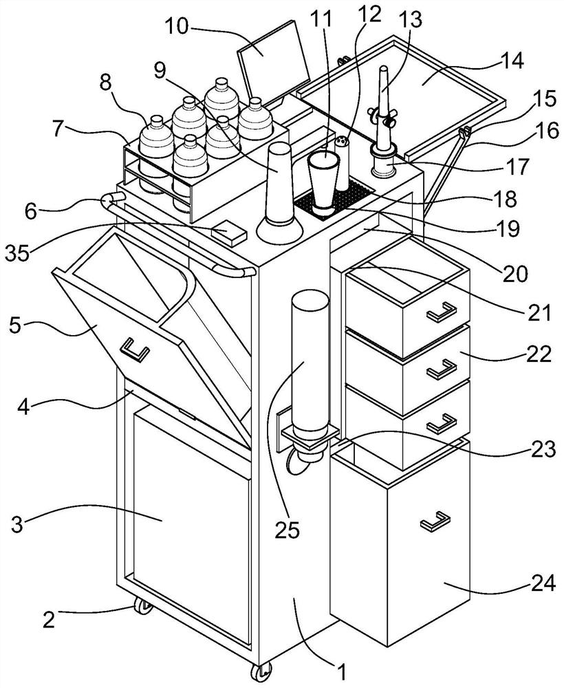
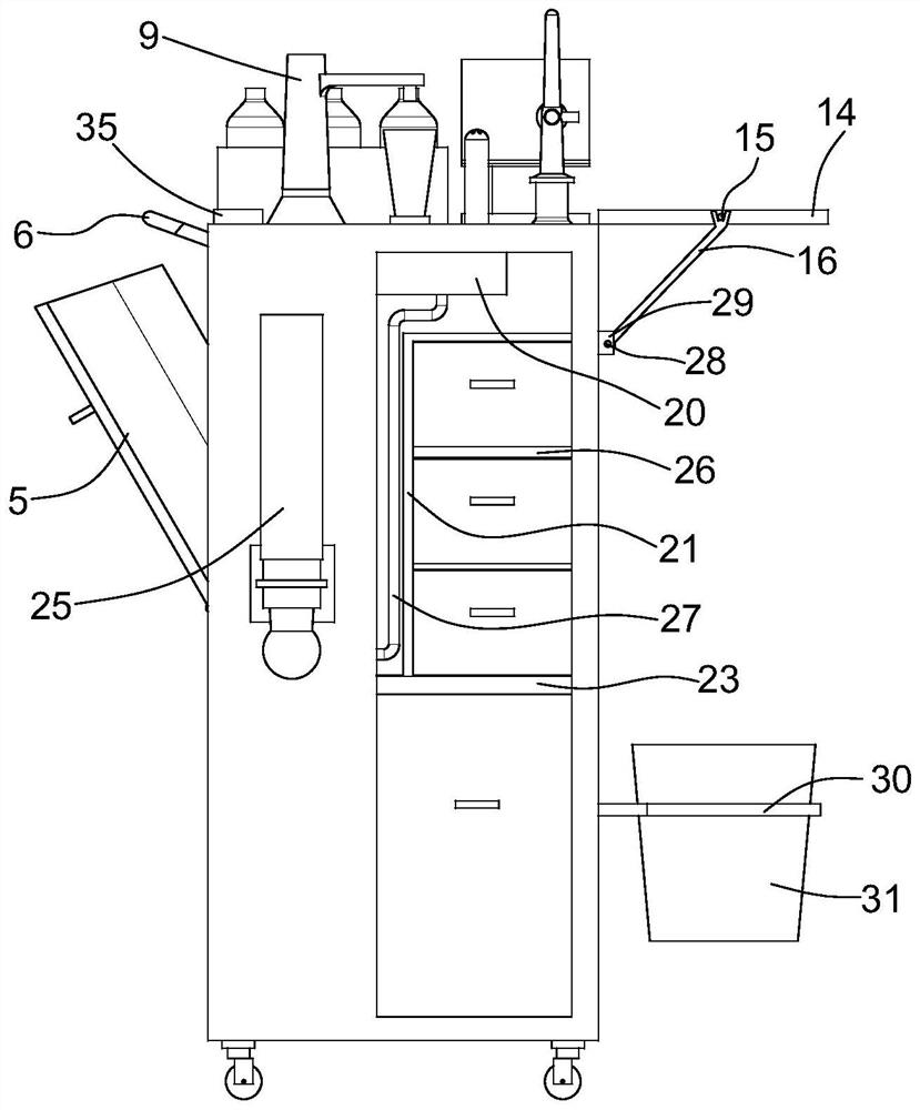
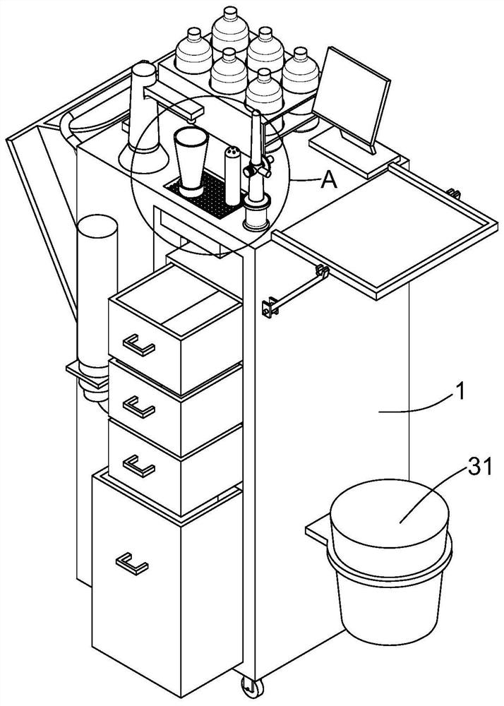
[0034] Please refer to Figure 1 to Figure 5 , a sterile humidification liquid filling vehicle, including such as figure 1The shown hollow cuboid car body 1 is provided with a vertical plate 32 that divides it into a recovery area and a storage area in the horizontal direction in the car body 1, and also includes a draining area 18 arranged on the top of the car body 1, adding Fluid components and auxiliary components. The recycling area is provided with a first partition 4 longitudinally dividing it into a dry matter part and a waste liquid part, and the draining area 18 communicates with the waste liquid part. In this embodiment, the draining area 18 is used to dump the remaining humidification liquid in the used humidification bottle 11, and the liquid filling component is used to fill the newly replaced humidification bottle 11 with sterile humidification liquid, and the auxiliary components are used For placing the accessories of the buoy type oxygen inhaler, the dry pa...

Embodiment 2

[0045] This embodiment is a further improvement on Embodiment 1, and repeated content will not be repeated here.

[0046] In this example, if Figure 4 and Figure 7 As shown, the bottom of the drain tank 181 is provided with several grooves 183. In this embodiment, the grooves 183 are U-shaped grooves. In other embodiments, the grooves 183 can be V-shaped grooves or arc grooves. A plurality of evenly distributed first drain holes 182 are disposed through the bottom of the groove 183 . The groove 183 is convenient for fully emptying the waste wetting liquid from the bottom of the draining tank 181. The opening of the groove 183 reduces the planar area of ​​the bottom of the draining tank 181, thereby making the remaining waste wetted at the bottom of the draining tank 181 The reduced liquid volume facilitates the cleaning of the drain tank 181 and reduces the risk of cross-infection.

Embodiment 3

[0048] This embodiment is a further improvement on Embodiment 2, and repeated content will not be repeated here.

[0049] Such as Figure 4 and Figure 8 As shown, several grooves 183 are distributed in parallel, and a protrusion 184 is formed between two adjacent grooves 183 , and the top of the protrusion 184 is in the shape of an outwardly convex arc. In this embodiment, the convex portion 184 in the shape of an arc makes the plane area of ​​the bottom of the draining tank 181 zero, and when the waste humidification liquid is poured into the draining tank 181, no waste will appear at the bottom of the draining tank 181. Moisturizing fluid remains.


PUM


Abstract

The invention provides a sterile humidifying liquid adding vehicle which comprises a vehicle body, a vertical plate dividing the vehicle body into a recycling area and a storage area in the horizontal direction is arranged in the vehicle body, and the sterile humidifying liquid adding vehicle further comprises a liquid draining area, a liquid adding assembly and an auxiliary assembly which are arranged on the upper portion of the vehicle body. A first partition plate for longitudinally dividing the recovery area into a dry part and a waste liquid part is arranged in the recovery area, and the liquid draining area is communicated with the waste liquid part; the liquid draining area is used for pouring remaining humidification liquid in a used humidification bottle, the liquid adding assembly is used for adding sterile humidification liquid into a newly-replaced humidification bottle, the auxiliary assembly is used for containing accessories of the float type oxygen inhalator, the dry object part is used for recycling the used humidification bottle, and the waste liquid part is used for collecting residual humidifying liquid poured from the used humidifying bottle. The sterile humidifying liquid adding vehicle can assist medical staff in accurately and rapidly injecting sterile humidification liquid, the hospital infection risk of the humidification bottle can be reduced, and the working efficiency of the medical staff is effectively improved.

Description

technical field [0001] The invention relates to the technical field of medical devices, in particular to a sterile humidification fluid filling vehicle. Background technique [0002] The buoy type oxygen inhaler is a basic oxygen supply device for providing emergency oxygen supply or oxygen therapy to hypoxic patients in clinical treatment, and it is widely used in medical institutions. After the medical oxygen is physically mixed with the humidification liquid in the humidification bottle of the inhaler, it becomes humidified oxygen, which enters the body through the patient's respiratory tract, so as to prevent the patient from directly inhaling oxygen into the body and causing discomfort. At present, medical institutions stipulate that the humidification fluid of the buoy type oxygen inhaler should be replaced after 24 hours of use, and the humidification bottle should be "one person, one use, one disinfection" to avoid cross-infection of the device and affect the health ...

Claims


Application Information

Patent Timeline
Patent Type & Authority Applications(China)
IPC IPC(8): A61M16/16A61G12/00
CPCA61G12/001A61M16/16A61M16/162A61M2205/60A61M2205/6009
Inventor 黄琪杰张毅强吴孟航任秋平杨小玲赵聪
Owner WEST CHINA HOSPITAL SICHUAN UNIV
Why Eureka
Try Eureka