Machine tool laser compensation device for slender shaft machining and compensation method conducted though machine tool laser compensation device

A compensation device, slender shaft technology, applied in metal processing machinery parts, metal processing equipment, manufacturing tools, etc., can solve the problems of reduced accuracy, bending deformation, poor rigidity of the slender shaft, etc. Large deformation, the effect of preventing workpiece deformation

A compensation device, slender shaft technology, applied in metal processing machinery parts, metal processing equipment, manufacturing tools, etc., can solve the problems of reduced accuracy, bending deformation, poor rigidity of the slender shaft, etc. Large deformation, the effect of preventing workpiece deformation

CN112719951AInactive Publication Date: 2021-04-30PINGDINGSHAN UNIVERSITY

Image

  • Machine tool laser compensation device for slender shaft machining and compensation method conducted though machine tool laser compensation device
  • Machine tool laser compensation device for slender shaft machining and compensation method conducted though machine tool laser compensation device
  • Machine tool laser compensation device for slender shaft machining and compensation method conducted though machine tool laser compensation device

Examples


Embodiment Construction

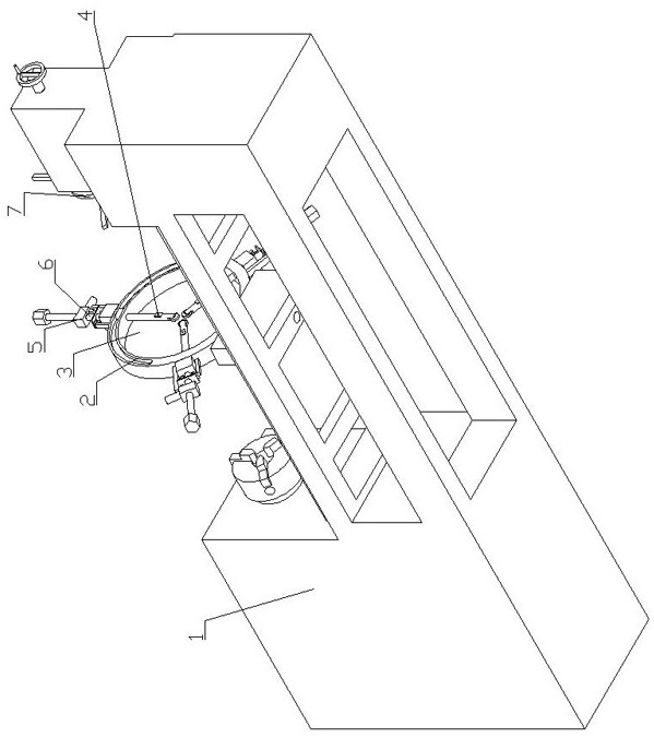
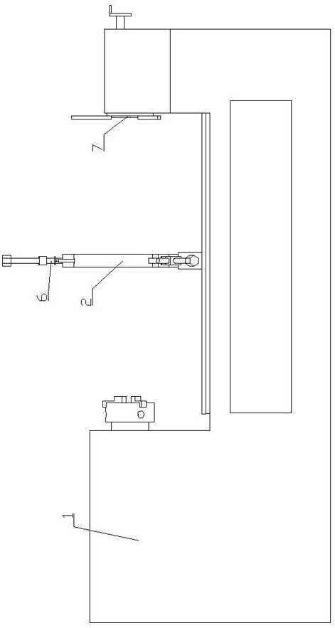
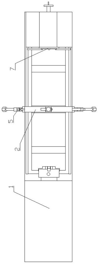
[0043] Machine tool laser compensation device for slender shaft processing, such as Figure 1-7 As shown, the self-compensating steady rest 2 is included, and the self-compensating steady rest 2 is fixedly arranged on the machine tool 1 . The fixed position of the self-compensating steady rest 2 on the machine tool 1 is: located at the center of the longitudinal direction of the machine tool 1 to ensure that the workpiece can pass through the self-compensating steady rest 2 when it is on the machine tool 1 .

[0044] The cross-section of the self-compensating center frame 2 is circular. On the self-compensating center frame 2, a tank body 3 is arranged along the thickness direction of the self-compensating center frame 2. The tank body 3 is circular, and the dots of the tank body 3 are aligned with the self-compensating center frame. The dots of the center frame 2 coincide.

[0045] A support rod 8 is slidably arranged on the self-compensating center frame 2, and the support ...


PUM


Abstract

The invention discloses a machine tool laser compensation device for slender shaft machining and a compensation method conducted though the machine tool laser compensation device. The device comprises a self-compensation center frame, springs, supporting rods, lead screws and motors. The self-compensation center frame is provided with a groove body which is formed in the thickness direction of the self-compensation center frame in a penetrating manner, and the groove body is round. The springs are arranged on the supporting rods in a sleeving manner and located on the outer side of the self-compensation center frame, one end of each spring is connected with the corresponding supporting rod, the other ends of the springs are connected to the self-compensation center frame, and the supporting rods are arranged on the self-compensation center frame in a sliding manner and arranged in the axial direction of the groove body. The first ends of the supporting rods face the center of the groove body, the second ends of the supporting rods are connected with nuts, the nuts are in threaded connection to the lead screws, and the lead screws are in transmission connection with the motors. According to the machine tool laser compensation device for slender shaft machining, the problem that when a slender shaft is turned and machined, machining precision is affected due to bending deformation of a workpiece can be solved, the response speed is high, and accurate compensation resetting can be conducted through a reverse compensation method.

Description

technical field [0001] The invention belongs to the technical field of machine tool processing, and in particular relates to a machine tool laser compensation device for slender axis processing and a compensation method using the same. Background technique [0002] Slender shafts are relatively common in industrial production. In order to process the slender shafts to meet the needs of subsequent production, it is usually necessary to set the slender shafts on a machine tool and turn the slender shafts through the machine tool. [0003] Due to the poor rigidity of the slender shaft, when the slender shaft is turned by the machine tool, under the combined action of the gravity of the slender shaft itself, the cutting force of the turning tool and the centrifugal force of high-speed rotation, the slender shaft will bend, which will affect the turning of the workpiece precision. [0004] When the workpiece is being processed, system excitation will occur. The system excitation...

Claims


Application Information

Patent Timeline
30 Apr 2021
Publication
CN112719951A
IPC
B23Q1/76; B23Q17/24; B23Q17/22
CPC
B23Q1/76; B23Q17/2428
Inventors
杨立权; 吕青青