CCD positioning and correcting die-cutting machine

A die-cutting machine and die-cutting technology, which is applied to conveyor objects, metal processing, winding strips, etc., can solve the problems of reducing die-cutting accuracy, the camera cannot move independently, and the characteristics of the CCD adjustment mechanism are not specifically disclosed.

Active Publication Date: 2021-04-30
GUANGDONG FXD INTELLIGENT EQUIP CO LTD
View PDF7 Cites 1 Cited by
  • Summary
  • Abstract
  • Description
  • Claims
  • Application Information

AI Technical Summary

Problems solved by technology

The die-cutting machine can adjust the upper die base in the horizontal direction without stopping the machine through the adjustment mechanism, which improves the die-cutting accuracy and efficiency. However, during the position adjustment process of the CCD camera position adjustment mechanism in this equipment, The two groups of CCD cameras move synchronously in the X-axis direction, and the two groups of cameras cannot move independently, and the position adjustment mechanism of the CCD cameras is easily displaced by force during work, which reduces the precision of die-cutting. At the same time, the die-cutting part and the Both the pulling components produce a compressive force on the material. When the die-cutting part is die-cutting, the material of the pulling component is affected by the die-cutting to generate tension, which will cause wear on the surface of the material.
[0004] Chinese patent document CN110919766A discloses a kind of CCD die-cutting machine, comprises workbench, frame, computer; The blanking mechanism is set on the alignment platform for pulling processing materials; the die-cutting mechanism is set between the feeding mecha...

Method used


Image

  • CCD positioning and correcting die-cutting machine
  • CCD positioning and correcting die-cutting machine
  • CCD positioning and correcting die-cutting machine

Examples


Embodiment 1

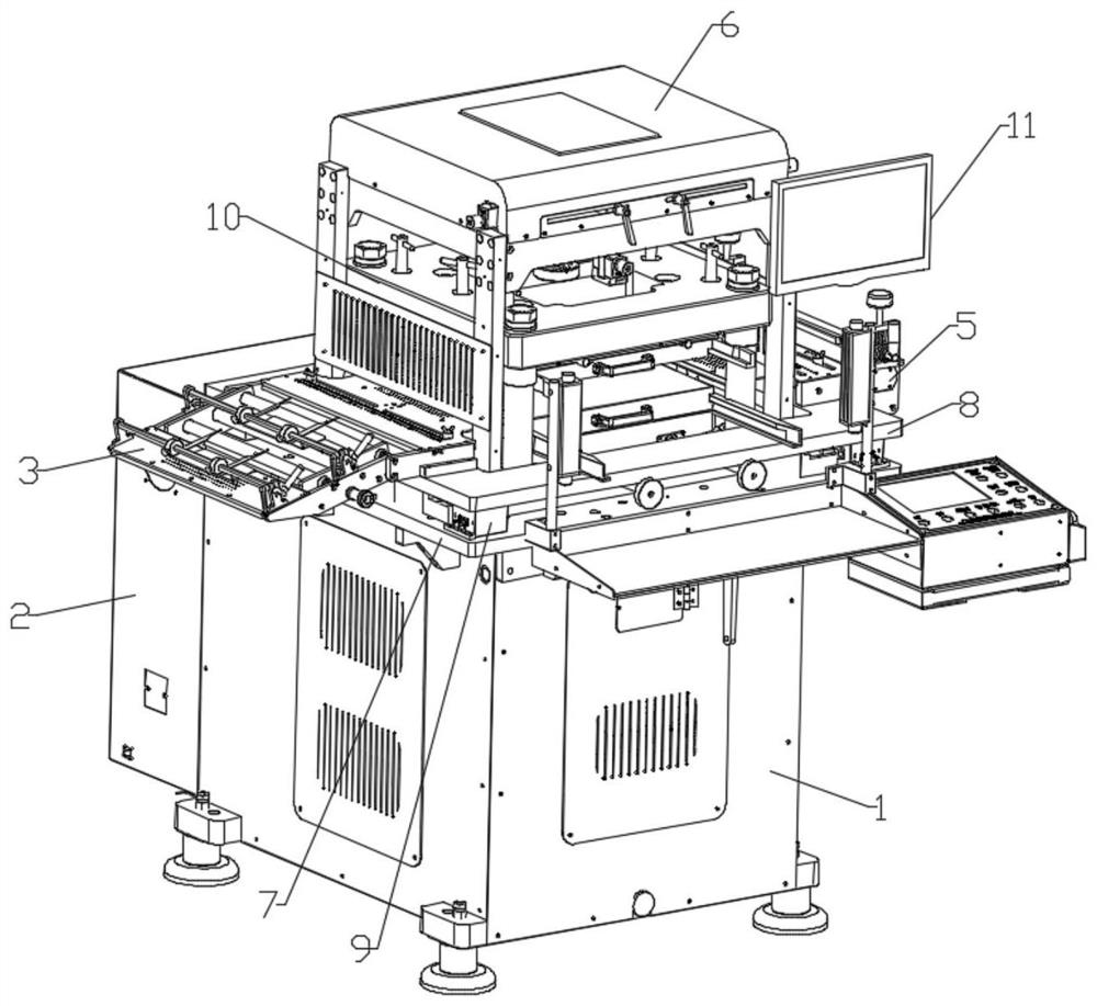
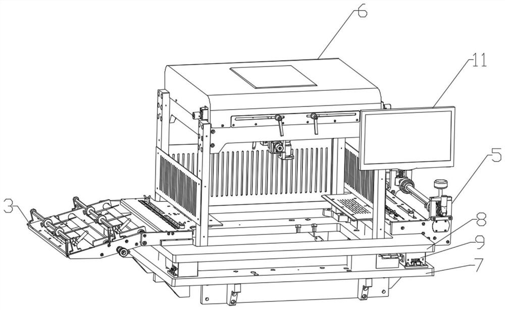
[0046] combine Figure 1-2 As shown, a CCD positioning correction die-cutting machine is disclosed in this embodiment, including a die-cutting host 1 for the die-cutting process, a power chassis 2 for providing power for the die-cutting machine, and a feeder for material feeding Component 3, a material pulling component 5 for material discharge and material transmission power, and a visual positioning mechanism 6 for locating the position of the material in the die-cutting host. The bottom of the die-cutting host 1 is provided with four sets of supporting bases. The supporting base is used to keep the die-cutting main machine 1 stably placed on the level ground, the power chassis 2 is installed on the rear side of the die-cutting main machine 1, and the feeding assembly 3 and the pulling assembly 5 are relatively installed on the die-cutting main machine 1 The visual positioning mechanism 6 is installed directly above the die-cutting host 1 .

[0047] Specifically, the die-cu...


PUM


Abstract

The invention relates to a CCD (Charge Coupled Device) positioning and correcting die-cutting machine which comprises a die-cutting main machine used in a die-cutting process, a power case used for providing power for the die-cutting machine, a feeding assembly used for feeding materials, a pulling assembly used for discharging the materials and providing material transmission power, and a visual positioning mechanism used for positioning the materials in the die-cutting main machine, The die-cutting main machine is stably placed on the horizontal ground, the power case is installed on the rear side face of the die-cutting main machine, the feeding assembly and the material pulling assembly are oppositely installed on the two sides of the die-cutting main machine, and the visual positioning mechanism is installed over the die-cutting main machine. According to the die-cutting machine, the two sets of X-axis driving mechanisms and the two sets of Y-axis driving mechanisms which are independently controlled are utilized, each camera is rapidly, conveniently and independently adjusted to any position in the horizontal direction, in the adjusting process, shaking of the CCD camera is small, and the positioning precision is higher.

Description

technical field [0001] The invention relates to the technical field of die-cutting equipment, in particular to a CCD positioning deviation correcting die-cutting machine. Background technique [0002] The die-cutting machine is mainly used for die-cutting (full cut, half cut) of some non-metallic materials, self-adhesive, EVA, double-sided tape, electronics, mobile phone rubber pads and other materials. For the die-cutting machine, its main working principle is: a motor drives the eccentric spindle to rotate, and the eccentric spindle drives the upper mold base, relative to the stationary lower mold base, vertical reciprocating motion, there is a matching gap between the upper and lower mold bases. Upper and lower templates and cutters. When the punched coil is driven by the pulling mechanism and passes through the upper and lower die seats according to the design speed, when the die-cutting upper die and the die-cutting lower die are closed according to the law, the punchi...

Claims


Application Information

Patent Timeline
IPC IPC(8): B26F1/40B26D5/14B26D7/26B26D7/27B65G47/22B65H23/02
CPCB26D5/14B26D7/2628B26D7/27B26F1/40B65G47/22B65H23/0204
Inventor 侯立新喻强军
Owner GUANGDONG FXD INTELLIGENT EQUIP CO LTD
Why Eureka
Try Eureka