Sidewalk drainage structure and combined drainage method of sidewalk drainage structure and drainage kerbs

A technology for drainage structures and sidewalks, which is applied to drainage structures, side ditches/curbs, roads, etc., can solve problems such as affecting the safety of driving and pedestrians, increasing the drainage pressure on the road surface, and the long path of rainwater infiltration, saving materials, The effect of short infiltration path and pressure relief

Active Publication Date: 2021-04-30
CHINA POWER CONSRTUCTION GRP GUIYANG SURVEY & DESIGN INST CO LTD
View PDF5 Cites 2 Cited by
  • Summary
  • Abstract
  • Description
  • Claims
  • Application Information

AI Technical Summary

Problems solved by technology

At present, the sidewalks on both sides of the road mostly use 3-6cm permeable bricks + 2-3cm cement mortar or medium-coarse sand + 8-12cm C15 or C20 plain concrete + 10-15cm graded gravel to infiltrate and drain rainwater below the surface. Drainage, however, this kind of drainage structure has a certain effect when the rainfall is small and does not form runoff or the sidewalk and walkway have been soaked by rainwater. When it rains and the rainfall lasts for a long time, due to the long rainwater infiltration path of the existing sidewalk structure, most of the rainwater will directly flow into the carriageway in the form of runoff before infiltration, which increases the drainage pressure of the road surface and affects driving and transportation. Pedestrian safety; in addition, the current curbs on both sides of the sidewalk are mainly prefabricated concrete blocks or stone processing, and its structure and function are too single. Structure and method for drainage

Method used


Image

  • Sidewalk drainage structure and combined drainage method of sidewalk drainage structure and drainage kerbs
  • Sidewalk drainage structure and combined drainage method of sidewalk drainage structure and drainage kerbs
  • Sidewalk drainage structure and combined drainage method of sidewalk drainage structure and drainage kerbs

Examples


Embodiment Construction

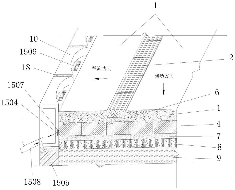
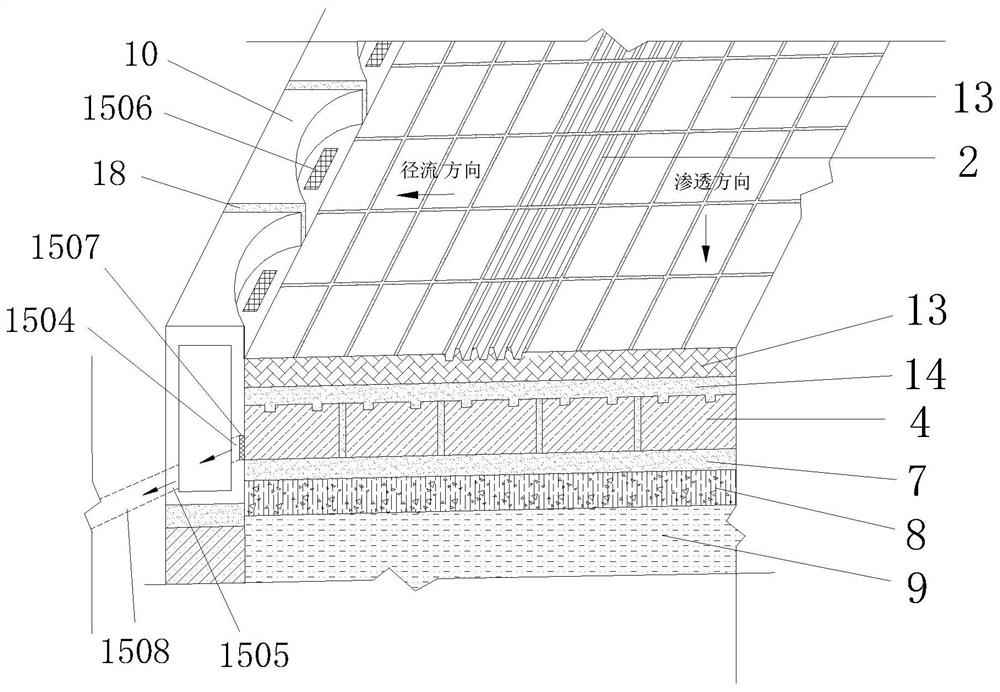
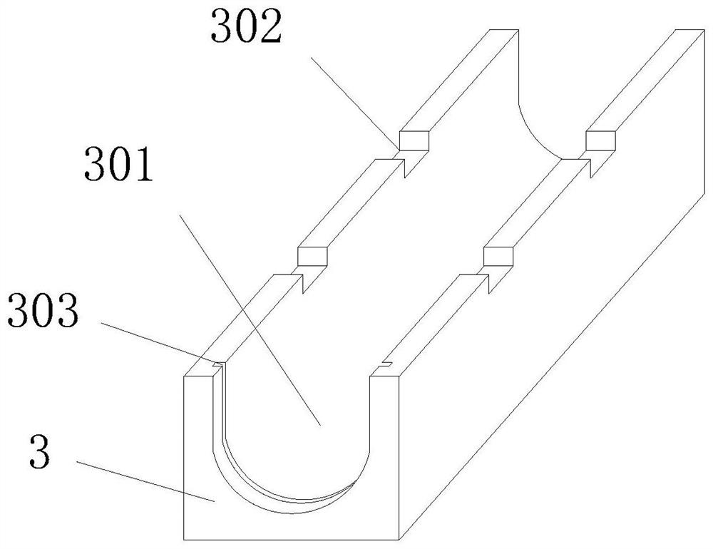
[0050]In order to make the objects, technical solutions and advantages of the present invention more clear, the following will be incorporatedfigure 1 AdherentFigure 12 Detailed description will be further described in detail in the specific embodiments of the present invention.

[0051]Such asFigure 1 to 12 As shown, it is a human sidewalk drainage structure and its combined drainage method with the drainage rock stone, first look at the first human sidewalk drainage structure, the sidewalk drainage structure is made of water-shaped concrete 1 and several pieces of water blind bricks 2 constitute an osmotic drainage surface Layer, a layer of permeable drainage block 3, a second drain block 4, and a grade gravel or crushed block 4, and a permeable drainage brick 2 and a permeate drainage base layer below The first cement mortar layer 6 and the second cement mortar are respectively laid, respectively, and the portion of the second cement mortar is located below the second cement mortar ...


PUM


Abstract

The invention discloses a sidewalk drainage structure and a combined drainage method of the sidewalk drainage structure and a drainage kerb. The sidewalk drainage structure is characterized in that permeable concrete and a plurality of permeable blind road bricks form a permeable drainage surface layer; a permeable drainage base layer composed of a plurality of first drainage building blocks, a plurality of second drainage building blocks and graded broken stones or broken gravels is arranged below the permeable concrete, and a first cement mortar leveling layer and a second cement mortar leveling layer are laid below the permeable blind road bricks and the permeable drainage base layer respectively. A concrete cushion layer is arranged at the part below the second cement mortar leveling layer, and a compacted soil foundation is arranged below the concrete cushion layer. The sidewalk drainage structure has the advantages of being short in infiltration path, simple in structure, convenient to construct, capable of saving materials, obvious in economical efficiency and the like, and in addition, the invention further provides a drainage kerb structure. Therefore, rainwater on the surface of a road in a sidewalk or a square footpath provided with kerbs and infiltrated rainwater are directly led into the kerbs.

Description

Technical field[0001]The present invention belongs to the technical field of traffic infrastructure, and involves a human sidewalk drainage structure and its combined drainage method with drainage rock.Background technique[0002]In recent years, urban flood disasters often occur in Beijing, Guangzhou, Wuhan, Nanjing, Shenzhen, Chongqing and other cities. The main reason is that it is affected by global warming, the temperature rise increases the water content of the atmosphere, the atmosphere The water capacity is constantly enhanced. Once the air-containing water is sufficient to meet the rainfall conditions, it will produce heavy rainfall; the second is to continue to advance with the urbanization process, urban roads and square area are also increasing, resulting in a large increase in the inflatable area, The reduction in rain is reduced. Once the heavy rainfall or the long-lasting duration is very easy to cause the drainage drainage system less than the traffic volume of the roa...

Claims


Application Information

Patent Timeline
Patent Type & Authority Applications(China)
IPC IPC(8): E01C11/22E03F5/046E03F5/14
CPCE01C11/225E01C11/222E03F5/046E03F5/14
Inventor 曹世江吴飞李健刘斌李洋徐显芬刘君韬龙康滔杨亮张晓娇陈德永张震熊仕吉李少展
Owner CHINA POWER CONSRTUCTION GRP GUIYANG SURVEY & DESIGN INST CO LTD
Why Eureka
Try Eureka