
Perforating device for constructional engineering

A drilling device and construction engineering technology, applied in construction, drilling equipment and methods, drilling equipment, etc., can solve the problems of energy consumption and high friction for drilling, and achieve reduced energy consumption, reduced friction, and improved drilling efficiency. Effect of Pore Efficiency

Pending Publication Date: 2021-04-30
LUSHAN COLLEGE OF GUANGXI UNIV OF SCI & TECH
View PDF9 Cites 0 Cited by
  • Summary
  • Abstract
  • Description
  • Claims
  • Application Information

AI Technical Summary

Problems solved by technology

[0002] During the building construction process, it is necessary to use devices to drill holes in the foundation for subsequent engineering construction. When some existing devices drill holes in the foundation, the friction between the drill bit and the rotating shaft, the inner wall of the hole and the drilled soil is relatively large, which not only consumes Drilling energy, at the same time as the depth of drilling increases, the friction gradually increases, so only shallower holes can be drilled

Method used


Image

  • Perforating device for constructional engineering
  • Perforating device for constructional engineering
  • Perforating device for constructional engineering

Examples


Embodiment Construction

[0029] The following will clearly and completely describe the technical solutions in the embodiments of the present invention with reference to the accompanying drawings in the embodiments of the present invention. Obviously, the described embodiments are only some of the embodiments of the present invention, not all of them. The following description of at least one exemplary embodiment is merely illustrative in nature and in no way taken as limiting the invention, its application or uses.

[0030] To keep the following description of the embodiments of the present invention clear and concise, detailed descriptions of known functions and known components are omitted from the present invention.

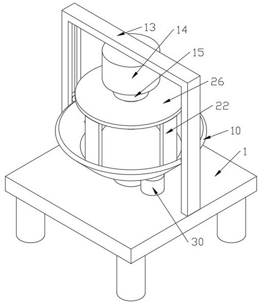
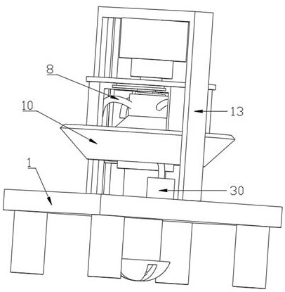
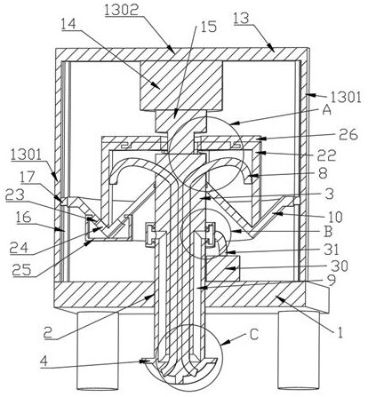
[0031] see Figure 1-6 As shown, in this embodiment, a punching device for construction engineering is provided, including: an operating table 1, a first hole 2 is provided on the upper end of the operating table 1, and a rotating shaft 3 is movably fitted in the first hole 2, and the...


PUM


Abstract

The invention discloses a perforating device for constructional engineering, and relates to the technical field of constructional engineering perforating. The perforating device comprises an operation table, a first hole is formed in the upper end of the operation table, a rotating shaft is movably matched in the first hole, a drill bit is arranged at the bottom end of the rotating shaft, the diameter of the rotating shaft is smaller than that of the drill bit, and a drill groove is formed in the bottom of the drill bit. According to the perforating device, drilled soil is driven to enter the drilling groove and a discharging pipe through rotation of the drill bit, then an air inlet assembly is started, air enters the discharging pipe through a third groove channel to be blown, the soil in the discharging pipe slides upwards and then falls into a collecting hopper, the downward pressure of the rotating shaft is increased, and meanwhile the drilled soil is conveniently collected; and meanwhile, the resistance of soil drilled by the drill bit to the drill bit when the drill bit continuously drills downwards is reduced, the drilling efficiency is improved, the energy consumption required by drilling is reduced, the friction force between rotation of the rotating shaft and the inner wall of a drilled hole and drilled soil is reduced by setting the diameter of the rotating shaft to be smaller than that of the drill bit, deep holes are conveniently drilled, and the drilling efficiency is improved.

Description

technical field [0001] The invention belongs to the technical field of construction engineering drilling, in particular to a drilling device used in construction engineering. Background technique [0002] During the building construction process, it is necessary to use devices to drill holes in the foundation for subsequent engineering construction. When some existing devices drill holes in the foundation, the friction between the drill bit and the rotating shaft, the inner wall of the hole and the drilled soil is relatively large, which not only consumes At the same time, the friction force gradually increases with the depth of drilling, so only shallow holes can be drilled. Contents of the invention [0003] The object of the present invention is to provide a kind of drilling device for construction engineering, through the rotation of the drill bit, the drilled soil is driven into the drilling groove and the discharge pipe, and then the air intake assembly is opened, an...

Claims


Application Information

Patent Timeline
Patent Type & Authority Applications(China)
IPC IPC(8): E21B7/00E21B21/16E21B21/01E21B21/07E21B10/60
CPCE21B7/00E21B21/16E21B21/01E21B21/07E21B10/60Y02P70/10
Inventor 吴长清张娜周金华
Owner LUSHAN COLLEGE OF GUANGXI UNIV OF SCI & TECH
Learn More