Omni-bearing mobile investigation detector, control system and control method

An all-round mobile and detector technology, applied in the field of drones, can solve problems such as poor endurance, poor mobility, and limited functions, and achieve the effects of strong mobility, improved mobility, and strong functionality

Active Publication Date: 2021-04-30
GUANGDONG UNIV OF TECH
View PDF4 Cites 0 Cited by
  • Summary
  • Abstract
  • Description
  • Claims
  • Application Information

AI Technical Summary

Problems solved by technology

First of all, they have a single structure and poor maneuverability. Most of them use air rotor racks. Therefore, they are subject to complex and changeable geographical environments. If they cannot effectively complete real-time reconnaissance and detection tasks in water environment, this greatly reduces their reconnaissance scope.
Secondly, they have limited functions and lack of flexibility. For example, it is difficult to complete the arduous task of searching and reconnaissance in the woods at night, and at the same time, their battery life is poor, so they often need to consume a lot of manpower and material resources.
Finally, this type of system currently often uses a traditional single inertial measurement element to collect data to complete the attitude calculation, which makes it difficult to collect more accurate sensor data for calculation in the complex and changeable environment across water, land and air to obtain the optimal attitude. Attitude solution, therefore, this makes the body attitude of this type of unmanned reconnaissance detection system unable to effectively achieve strong anti-disturbance control during flight operations such as water-air environment switching, and affects the motion planning task of the entire system to a large extent.

Method used


Image

  • Omni-bearing mobile investigation detector, control system and control method
  • Omni-bearing mobile investigation detector, control system and control method
  • Omni-bearing mobile investigation detector, control system and control method

Examples


Embodiment Construction

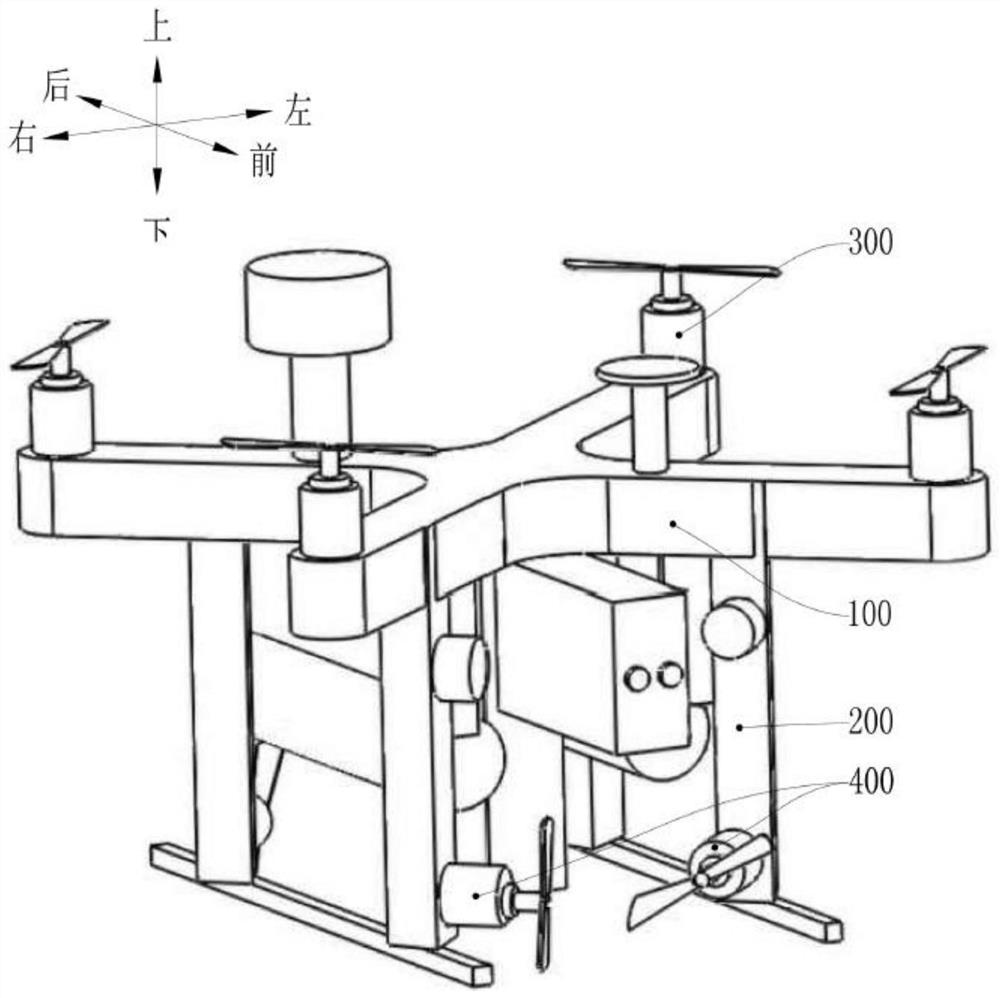
[0097] refer to figure 1 , the present invention discloses an omnidirectional mobile detection detector, including an X-shaped wing 100 , a mounting frame 200 , a main rotor assembly 300 and an auxiliary rotor assembly 400 . The mounting frame 200 is disposed on the lower surface of the X-shaped wing 100 . The four main rotor assemblies 300 are arranged on the upper end surfaces of the four ends of the X-shaped wing 100 in one-to-one correspondence. The rotor rotation axis of each main rotor assembly 300 is respectively perpendicular to the upper surface of the X-shaped wing 100 . The two auxiliary rotor assemblies 400 are arranged on the installation frame 200 . The two auxiliary rotor assemblies 400 are located on the same side of the X-shaped wing 100, the rotor rotation axes of the two auxiliary rotor assemblies 400 are on the same horizontal plane and are perpendicular to each other, the rotors of the two auxiliary rotor assemblies 400 The included angle between the ro...


PUM


Abstract

The invention discloses an omni-directional mobile investigation detector, a control system and a control method, and relates to the technical field of unmanned aerial vehicles. According to the omni-directional mobile investigation detector provided by the invention, on the basis of a fork-shaped quadrotor structure, two auxiliary rotor assemblies are additionally arranged to increase the torque, and through cooperation with four main rotor assemblies, the omni-directional mobile investigation detector not only can fly in the air, but also can flexibly move forwards, backwards, leftwards, rightwards, turns, longitudinally inclines forwards and backwards and the like in a water area environment, is high in maneuverability, is not limited by complex and changeable geographical environments, can realize aerial investigation and underwater detection, and is high in functionality. According to the invention, more accurate sampling data is obtained based on a fuzzy voting mechanism, and then the current pose information is calculated through an explicit complementary filtering algorithm, so that the omni-directional mobile investigation detector can realize strong disturbance rejection control of the body of the omni-directional mobile investigation detector in a long and narrow section and a torrent surge environment.

Description

technical field [0001] The invention relates to the technical field of unmanned aerial vehicles, in particular to an omnidirectional mobile detection detector, a control system and a control method. Background technique [0002] In recent years, with the rapid development of multi-rotor UAV technology, a wide variety of UAV reconnaissance detectors have emerged. This type of unmanned aerial vehicle system can not only complete certain land and air reconnaissance and detection tasks, but also complete corresponding real-time effective information feedback. But as far as the system technology that has been designed at present is concerned, they have many deficiencies. First of all, they have a single structure and poor maneuverability. Most of them use air rotor racks. Therefore, they are subject to complex and changeable geographical environments. If they cannot effectively complete real-time reconnaissance and detection tasks in water environment, this greatly reduces their...

Claims


Application Information

Patent Timeline
Patent Type & Authority Applications(China)
IPC IPC(8): G05D1/08G05D1/10
CPCG05D1/0808G05D1/101
Inventor 鲁仁全邓正雄徐雍林明饶红霞
Owner GUANGDONG UNIV OF TECH
Why Eureka
Try Eureka