Pulse ablation electrode assembly and pulse ablation catheter

An ablation electrode and ablation catheter technology are applied in the fields of pulse ablation electrode assemblies and pulse ablation catheters, and can solve the problems of poor ablation effect, large workload of linear ablation operations, and poor treatment effect.

Pending Publication Date: 2021-05-04
CHENGDU FLYER TECH CO LTD
View PDF0 Cites 1 Cited by
  • Summary
  • Abstract
  • Description
  • Claims
  • Application Information

AI Technical Summary

Problems solved by technology

If the voltage between the two electrodes is further reduced, the pulse intensity at the adjacent ends of the electrodes can meet the requirements, and the risk of scorching and scabbing caused by the adjacent ends of the two electrodes to human tissues can be prevented, that is, only between the outer edges of the two electrodes at the shortest distance If an electric field of consistent strength is generated in a small range, the pulse electric field at the end of the two electrodes away from each other and the side of the electrode is significantly lower than the required pulse electric field, and effective ablation cannot be achieved. In actual clinical pulse ablation, the effective pulse electric field space requires a volume that satisfies The pulsed electric field strength that meets the requirements is generated in the required electric field space. Usually, the electrodes inserted into the human body are small in size, the electric field space in the small range between the outer edges is too small, the ablation site is too small, the workload of linear ablation operation is huge, and the number of treatments is large. , the treatment effect is poor, and the ablation depth is not enough, and the overall ablation effect is poor or even ineffective. In order to ensure an effective electric field space, a large volume of electric field space is usually covered outside the entire electrode, and the electric field strength in this electric field space meets the ablation requirements. In the prior art, there is no effective technical solution to avoid the above-mentioned damage

Method used


Image

  • Pulse ablation electrode assembly and pulse ablation catheter
  • Pulse ablation electrode assembly and pulse ablation catheter
  • Pulse ablation electrode assembly and pulse ablation catheter

Examples


Embodiment Construction

[0028] Referring to the accompanying drawings, specific embodiments of the present invention will be described in detail.

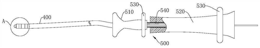
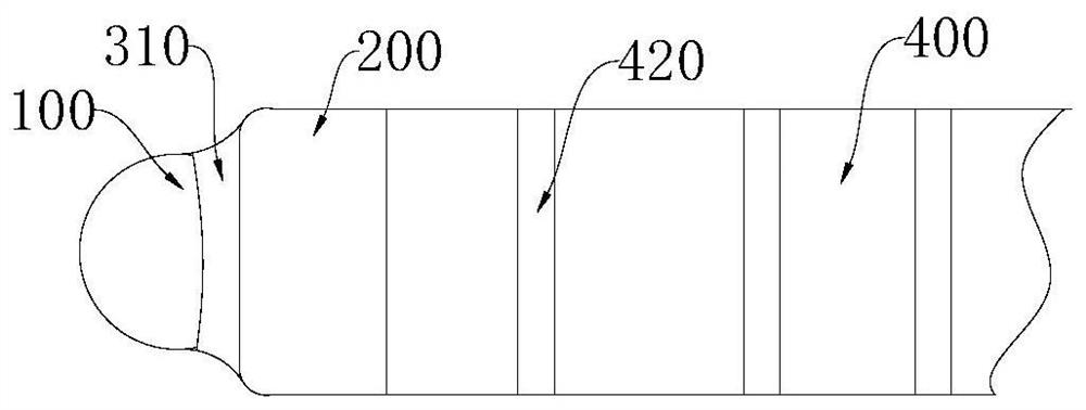
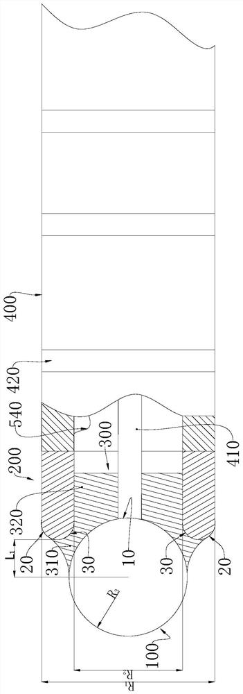
[0029] see Figure 1 to Figure 4, the first embodiment of the electrode assembly for pulse ablation, the electrode assembly for pulse ablation includes a first electrode 100 and a second electrode 200, the opposite ends of the two electrodes are protrusions 10 that gradually shrink, and the protrusions The surface is a curved surface to ensure a smooth transition of the entire electrode end, avoiding the tip effect, and the curved surface can be a positive curvature surface. The surface of the protrusion 10 can be a curved surface of revolution, the generatrix of the curved surface of revolution is a convex curve, and the slope of the convex curve section corresponding to the curved surface on the outer surface of the electrode smoothly transitioning to the top of the protrusion gradually becomes larger, ensuring that the protrusion Shrink effect for cur...


PUM


Abstract

The invention relates to a pulse ablation electrode assembly which comprises a first electrode and a second electrode, the opposite ends of the two electrodes are protrusions which shrink gradually, and an insulating layer is arranged between the opposite ends of the two electrodes. The invention also relates to a pulse ablation catheter. According to the invention, the pulsed electric field can be used for ablating tissues more safely, more effectively and more conveniently.

Description

technical field [0001] The invention relates to a medical device, in particular to a pulse ablation electrode assembly and a pulse ablation catheter. Background technique [0002] Radiofrequency ablation and cryoablation are two commonly used clinical methods for the treatment of arrhythmias and tumors. Nowadays, pulsed electric field technology has also appeared. Pulsed electric field technology applies a short high voltage to tissue cells, which can generate a local high electric field of hundreds of volts per centimeter: the local high electric field destroys the cell membrane by creating pores in the cell membrane. An applied electric field at the membrane greater than the cellular threshold causes the pore not to close, and this electroporation is irreversible, thereby allowing the exchange of biomolecular material across the membrane, resulting in necrosis or apoptosis. Pulse irreversible electroporation ablation is different from radio frequency, freezing, microwave,...

Claims


Application Information

Patent Timeline
IPC IPC(8): A61B18/12A61B18/14
CPCA61B18/12A61B18/1492A61B2018/00351A61B2018/00529A61B2018/00541A61B2018/00577A61B2018/00714A61B2018/00791A61B2018/1417A61B2018/1467
Inventor 洪光熊庆文谢志杰
Owner CHENGDU FLYER TECH CO LTD
Why Eureka
Try Eureka