Optical system, camera module and electronic equipment

A technology of optical system and optical axis, applied in the direction of optics, optical components, instruments, etc.

Active Publication Date: 2021-05-07
JIANGXI JINGCHAO OPTICAL CO LTD
View PDF4 Cites 5 Cited by
  • Summary
  • Abstract
  • Description
  • Claims
  • Application Information

AI Technical Summary

Problems solved by technology

[0003] Based on this, it is necessary to provide an optical system, a camera module and

Method used


Image

  • Optical system, camera module and electronic equipment
  • Optical system, camera module and electronic equipment
  • Optical system, camera module and electronic equipment

Examples


no. 1 example

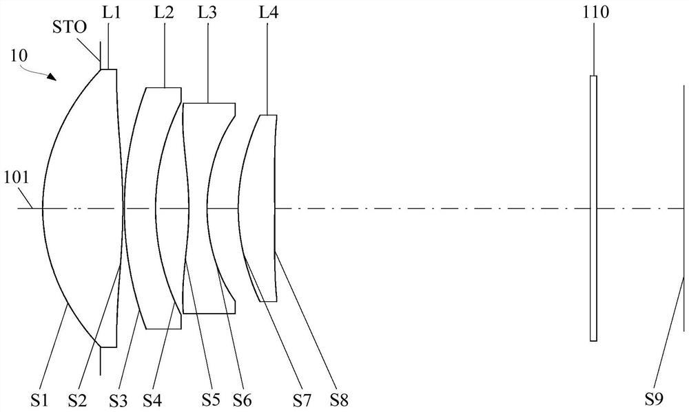
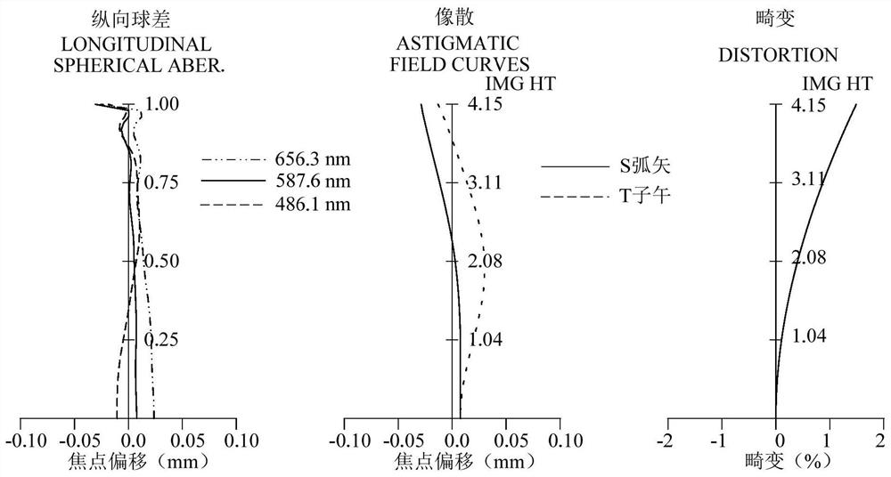
[0086] refer to figure 1 and figure 2 , in the first embodiment, the optical system 10 includes a stop STO, a first lens L1 with positive refractive power, a second lens L2 with negative refractive power, and a second lens L2 with negative refractive power from the object side to the image side along the optical axis 101. The third lens L3 with positive refractive power and the fourth lens L4 with positive refractive power. The first lens L1 and the second lens L2 form a lens group with positive refractive power, and the third lens L3 and the fourth lens L4 form a lens group with negative refractive power. figure 2 It includes the longitudinal spherical aberration diagram, astigmatism diagram and distortion diagram of the optical system 10 in the first embodiment, wherein the reference wavelength of the astigmatism diagram and distortion diagram is 587nm.

[0087]The object side S1 of the first lens L1 is convex at the paraxial position, and the image side S2 is convex at ...

no. 2 example

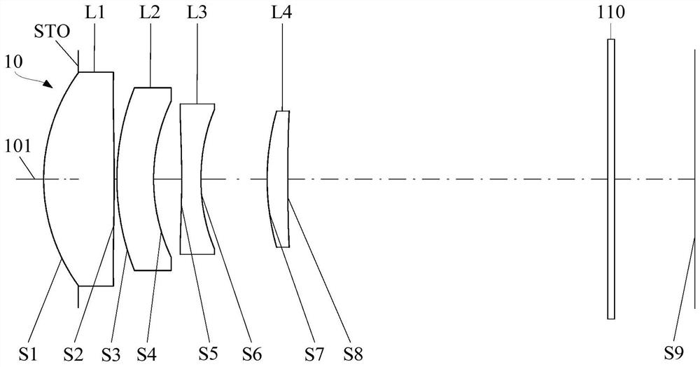
[0111] refer to image 3 and Figure 4 , in the second embodiment, the optical system 10 includes a diaphragm STO, a first lens L1 with positive refractive power, a second lens L2 with negative refractive power, and a second lens L2 with negative refractive power along the optical axis 101 from the object side to the image side. The third lens L3 with positive refractive power and the fourth lens L4 with positive refractive power. The first lens L1 and the second lens L2 form a lens group with positive refractive power, and the third lens L3 and the fourth lens L4 form a lens group with negative refractive power. Figure 4 It includes the longitudinal spherical aberration diagram, the astigmatism diagram and the distortion diagram of the optical system 10 in the second embodiment, wherein the reference wavelength of the astigmatism diagram and the distortion diagram is 587 nm.

[0112] The object side S1 of the first lens L1 is convex at the paraxial position, and the image ...

no. 3 example

[0125] refer to Figure 5 and Figure 6 , in the third embodiment, the optical system 10 includes a stop STO, a first lens L1 with positive refractive power, a second lens L2 with negative refractive power, and a second lens L2 with negative refractive power along the optical axis 101 from the object side to the image side. The third lens L3 with positive refractive power and the fourth lens L4 with positive refractive power. The first lens L1 and the second lens L2 form a lens group with positive refractive power, and the third lens L3 and the fourth lens L4 form a lens group with negative refractive power. Figure 6 The longitudinal spherical aberration diagram, astigmatism diagram and distortion diagram of the optical system 10 in the third embodiment are included, wherein the reference wavelength of the astigmatism diagram and distortion diagram is 587 nm.

[0126] The object side S1 of the first lens L1 is convex at the paraxial position, and the image side S2 is concav...


PUM

PropertyMeasurementUnit
Optical lengthaaaaaaaaaa

Abstract

The invention relates to an optical system, a camera module and electronic equipment. The optical system comprises, in order from an object side to an image side along an optical axis: a first lens element with positive refractive power; a second lens element with negative refractive power having an object-side surface being convex in a paraxial region thereof; a third lens element with negative refractive power having a concave image-side surface in a paraxial region thereof; a fourth lens element with positive refractive power having an object-side surface being convex in a paraxial region thereof; the optical system satisfies the following conditions: 0.5 < SD42/ImgH < 0.85, ImgH>4.0mm, SD42 is the maximum effective radius of the image side surface of the fourth lens, and ImgH is half of the image height corresponding to the maximum field angle of the optical system. By means of the design, on one hand, the system has the long-focus characteristic, on the other hand, aberration can be well restrained, the emergent angle of main light rays of an edge view field is restrained when the main light rays emerge from the fourth lens, and therefore the main light ray angle of an inner view field can be better matched with an image sensor.

Description

technical field [0001] The invention relates to the technical field of photography and imaging, in particular to an optical system, a camera module and electronic equipment. Background technique [0002] In the field of photography and imaging, the aberration of the system is generally corrected by adjusting the matching relationship between the lens parameters in the camera lens, or the imaging resolution of the camera module is improved by increasing the pixels of the image sensor. However, in order to effectively improve the imaging quality of the camera module, it is necessary to coordinate the configuration between the camera lens and the image sensor, so that the performance of the two can be fully reflected, thereby improving the imaging quality. How to better match the camera lens and the image sensor to improve the imaging quality is also one of the focuses of the industry. Contents of the invention [0003] Based on this, it is necessary to provide an optical sy...

Claims


Application Information

Patent Timeline
IPC IPC(8): G02B13/00G02B13/18
CPCG02B13/0015G02B13/004
Inventor 邹金华李明
Owner JIANGXI JINGCHAO OPTICAL CO LTD
Why Eureka
Try Eureka