
Large-current band-gap reference source

A high-current, reference source technology, applied in the direction of regulating electrical variables, control/regulating systems, instruments, etc., can solve problems such as lack of protection circuits, circuit damage, and doubts about circuit safety.

Pending Publication Date: 2021-05-07
南京瑞宽通信技术有限公司
View PDF0 Cites 0 Cited by
  • Summary
  • Abstract
  • Description
  • Claims
  • Application Information

AI Technical Summary

Problems solved by technology

[0003] The current bandgap reference circuits on the market often lack protection circuits, which makes the safety of the circuit questionable, and often leads to damage to the circuit, which needs to be improved.

Method used


Image

  • Large-current band-gap reference source
  • Large-current band-gap reference source
  • Large-current band-gap reference source

Examples


Embodiment 1

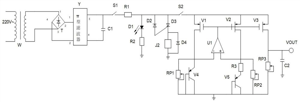
[0020] Example 1: See figure 1 , a high-current bandgap reference source, used to provide mains power supply for power supply, step-down rectifier filter module for changing high-voltage AC voltage to low-voltage DC voltage, and switch conduction module for circuit conduction. The overvoltage protection module for the circuit overvoltage disconnection circuit, the bandgap reference module for eliminating the influence of temperature, the output power supply module for outputting stable voltage, the mains power supply is connected to the step-down rectification filter module, and the step-down The rectification filter module is connected with the switch conduction module, the switch conduction module is connected with the overvoltage protection module, the overvoltage protection module is connected with the bandgap reference module, and the bandgap reference module is connected with the output voltage module.

[0021] Specific circuit such as figure 2 As shown, the step-down ...

Embodiment 2

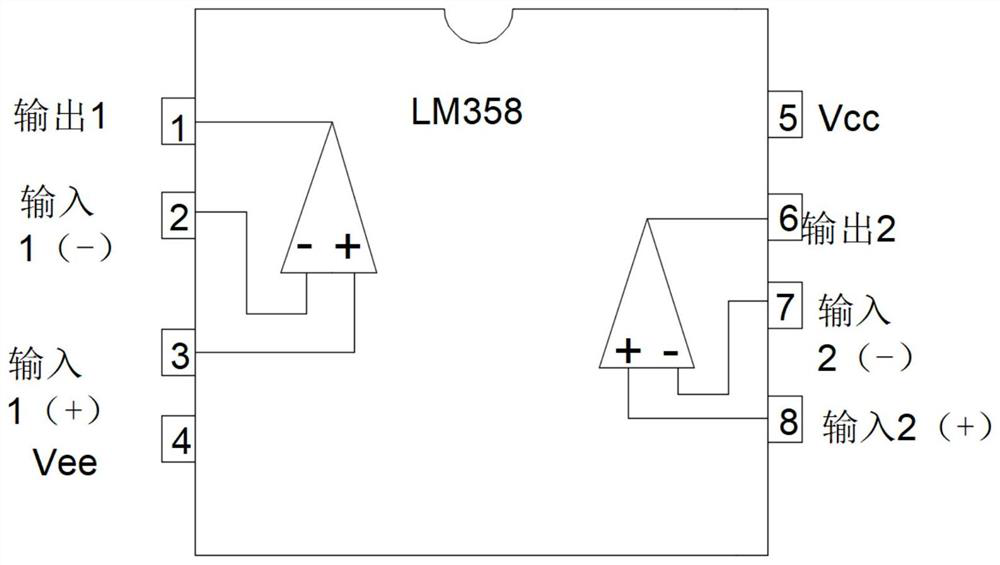
[0025] Embodiment 2, on the basis of embodiment 1, image 3 It is the pin diagram of amplifier LM358. LM358 has the following characteristics: internal frequency compensation, high DC voltage gain (about 100dB), unity gain frequency bandwidth (about 1MHz), wide power supply voltage range: single power supply (3-30V), dual power supply (±1.5-±15V), slew rate (0.3V / us) low power consumption current, suitable for battery power supply, low input bias current, low input offset voltage and offset current, wide common-mode input voltage range, including grounded differential mode The input voltage range is wide, which is equal to the supply voltage range, and the output voltage swing is large (0 to Vcc-1.5V).


PUM


Abstract

The invention discloses a large-current band-gap reference source. The reference source comprises a mains supply, a step-down rectifying and filtering module, a switch conduction module, an overvoltage protection module, a band-gap reference module and an output voltage module, the mains supply is connected with the step-down rectifying and filtering module, the step-down rectifying and filtering module is connected with the switch conduction module, the switch conduction module is connected with the overvoltage protection module, the overvoltage protection module is connected with the band-gap reference module, and the band-gap reference module is connected with the output voltage module. The reference source has the advantages that the overvoltage protection circuit is additionally arranged, so that the circuit can be disconnected under the overvoltage condition, and safe operation of the circuit is guaranteed; and meanwhile, a potentiometer is additionally arranged at the band-gap reference circuit to change the change between resistance values, so that the purpose of changing the output voltage is achieved.

Description

technical field [0001] The invention relates to a bandgap reference circuit, in particular to a large current bandgap reference source. Background technique [0002] The classic bandgap reference uses the sum of a voltage proportional to temperature and a voltage inversely proportional to temperature. The temperature coefficients of the two cancel each other out to achieve a temperature-independent voltage reference, which is about 1.25V. Because its reference voltage is similar to the bandgap voltage of silicon, it is called a bandgap reference. In fact, it is not the bandgap voltage that is used. Now some bandgap reference structure output voltage is not consistent with the bandgap voltage. The main problem to be solved to realize the reference voltage source is how to improve its temperature suppression and power supply suppression, that is, how to realize a structure that has a definite relationship with temperature and basically has nothing to do with power supply. S...

Claims


Application Information

Patent Timeline
IPC IPC(8): G05F1/56
CPCG05F1/561
Inventor 宋荣方
Owner 南京瑞宽通信技术有限公司
Learn More