Double-operational-amplifier elliptic function and inverse Chebyshev active low-pass filter circuit
An inverse Chebyshev, low-pass filter technology, applied in the field of analog microelectronics, can solve the problems of poor circuit symmetry and stability, small dispersion of component values, and large circuit volume, etc. The effect of cost, power consumption reduction, and circuit size reduction
- Summary
- Abstract
- Description
- Claims
- Application Information
AI Technical Summary
Problems solved by technology
Method used
Image
Examples
Embodiment 1
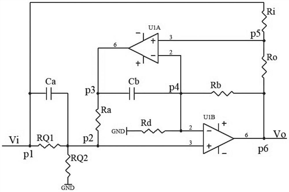
[0034] A dual op amp elliptic function, anti-Chebyshev active low-pass filter circuit, including signal input terminal Vs, signal output terminal Vo and input and output signal common terminal GND, is characterized in that, also includes resistance Rq1, resistance Rq2, resistance Ra, resistor Rb, resistor Rd, resistor Ri, resistor Ro, capacitor Ca, capacitor Cb, operational amplifier U1A and operational amplifier U1B, one end of resistor Rq1, resistor Ri and capacitor Ca is connected to node p1; as an input terminal connected to the input signal Vi; the other end of the resistor Rq1, the other end of the capacitor Ca, one end of the resistor Rq2 and the resistor Ra, and the non-inverting input end of the operational amplifier U1A are connected to the node p2; the other end of the resistor Rq2 is connected to the input and output signal common terminal GND; the resistor Ra The other end of the capacitor Cb, one end of the capacitor Cb, and the output of the op amp U1B are connec...
Embodiment 2
[0065] The present embodiment is the detailed circuit parameter example of 1KHz elliptic function low-pass filter:
[0066] A 5th-order elliptic function low-pass filter-amplifier, its cut-off frequency fc: 1KHz; passband fluctuation: 0.1dB; stopband attenuation: 60dB; transition bandwidth: 1.044fc; gain: maximized;
[0067] Obviously, you can use Figure 7 The scheme is realized, and the parameters of each filter section are as follows:
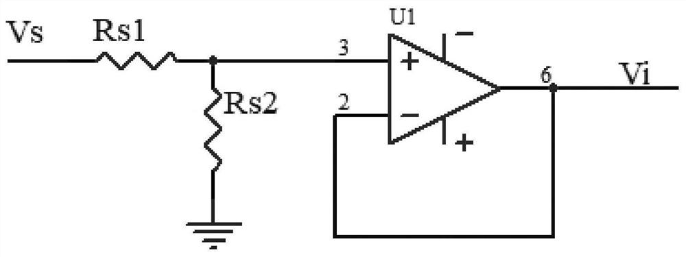
[0068] The first filter section: Op-amp isolation first-order RC low-pass filter section, circuit diagram: Figure 4 ;
[0069] Rs1=27K; C1=10nF
[0070] The second filter section: dual op amp second-order elliptic function low-pass filter section, circuit diagram: figure 1 ;
[0071] Ri=Ro=4.99K; Ca=Cb=10nF;
[0072] Ra=Rb=6.42K; Rd=7.96k; Rq1=Rq2=113K;
[0073] The third filter section: dual op amp second-order elliptic function low-pass filter section, circuit diagram: figure 1 ;
[0074] Ri=Ro=4.99K; Ca=Cb=10nF;
[0075] Ra=Rb=...
Embodiment 3
[0079] The present embodiment is the detailed circuit parameter example of 1KHz elliptic function low-pass filter:
[0080] Realize a 5th-order elliptic function low-pass filter with unity gain, 1KHz cut-off frequency, 0.1dB passband fluctuation, 60dB stopband attenuation, and excess bandwidth equal to 1.044 times the cut-off frequency.
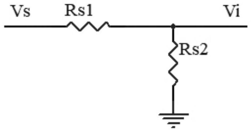
[0081] use Figure 9 Scheme, the value of the second-order filter section circuit components is the same as that of embodiment 2, and the first-order filter section adopts Figure 5circuit, the attenuation of the first-order filter section is equal to the total gain of all second-order filter sections, and the unity gain filter is obtained, and its circuit element values are: C1=10nF; Rs1=1665K; Rs2=27.5K;
[0082] Will Figure 11 The curve of is shifted down to the gain of 0 dB, that is, shifted down by 35.6 dB to obtain the frequency characteristic of this embodiment.
PUM
 Abstract
Description
Claims
Application Information
 - R&D
- Intellectual Property
- Life Sciences
- Materials
- Tech Scout
- Unparalleled Data Quality
- Higher Quality Content
- 60% Fewer Hallucinations
Browse by: Latest US Patents, China's latest patents, Technical Efficacy Thesaurus, Application Domain, Technology Topic, Popular Technical Reports.
© 2025 PatSnap. All rights reserved.Legal|Privacy policy|Modern Slavery Act Transparency Statement|Sitemap|About US| Contact US: help@patsnap.com


