Agricultural hay cutting, stirring and fattening device

Active Publication Date: 2021-05-11
JIANGXI WANGNONG AGRI MACHINERY MFG
View PDF13 Cites 1 Cited by
  • Summary
  • Abstract
  • Description
  • Claims
  • Application Information

AI Technical Summary

Problems solved by technology

[0004] In order to overcome the time-consuming and labor-intensive traditional manual mixing method, and the shortcomings of uneven manual mixing and low efficiency, the purpose of the present invention is to provide an agricultural jellyfish that relies on machine crushing, uniform feeding and stirring, reduces the amount of operation, and improves efficiency. Grass stirring and fattening device

Method used


Image

  • Agricultural hay cutting, stirring and fattening device
  • Agricultural hay cutting, stirring and fattening device
  • Agricultural hay cutting, stirring and fattening device

Examples


Embodiment 1

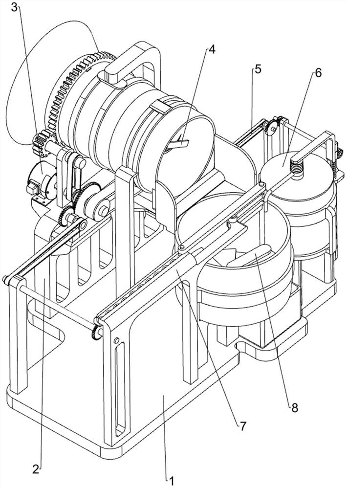
[0059] An agricultural chaff stirring and fattening device, such as Figure 1 to Figure 3 As shown, it includes a base 1, a first support frame 2, a material transfer mechanism 3 and a hay cutter mechanism 4, the rear side of the top of the base 1 is provided with a first support frame 2, and the top of the first support frame 2 is provided with a material transfer mechanism 3, The feeding mechanism 3 is provided with a hay cutting mechanism 4 .

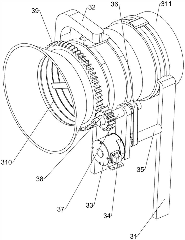
[0060]The feeding mechanism 3 includes a second support frame 31, a third support frame 32, a motor 33, a first fixed block 34, a first transmission rod 35, a first pulley set 36, a second transmission rod 37, a first gear 38, Ring gear 39, feed barrel 310 and discharge barrel 311, base 1 top is provided with second support frame 31, and second support frame 31 top is provided with discharge barrel 311, and first support frame 2 top right side is provided with third Bracing frame 32, the third supporting frame 32 tops are rotatably ...

Embodiment 2

[0064] On the basis of Example 1, such as Figure 4 and Figure 5 As shown, a transmission mechanism 5 is also included, and the transmission mechanism 5 includes a transmission assembly 51, a second gear 52, a third gear 53, a support seat 54, a fourth transmission rod 55, a second fixed seat 56, a fourth gear 57, First tooth bar 58, back-moving spring 59 and pressing plate 510, base 1 top right front side is provided with second fixed seat 56, and base 1 top right rear side is provided with support seat 54, between support seat 54 and second fixed seat 56 tops Rotation is connected with the fourth transmission rod 55, the fourth transmission rod 55 front side is provided with the fourth gear 57, the second fixed seat 56 top is connected with the return spring 59, the return spring 59 top is provided with the first rack 58, the first The tooth bar 58 is engaged with the fourth gear 57, the left side of the first tooth bar 58 is provided with a pressing plate 510, the rear si...

Embodiment 3

[0068] On the basis of Example 2, such as Figure 6 and Figure 7 As shown, a stirring mechanism 7 is also included, and the stirring mechanism 7 includes a fifth support frame 71, a sector gear 72, a fifth gear 73, a third fixed block 74, a second pulley set 75, a fifth transmission rod 76, a sixth Gear 77, the second rack 78, the sixth support frame 79, crank connecting rod group 710 and extension spring 711, the sector gear 72 is connected on the first transmission rod 35, the left side of the first support frame 2 top is provided with the third Fixed block 74, the third fixed block 74 upper rotating type is provided with the fifth gear 73, the fifth gear 73 meshes with the sector gear 72, the fifth support frame 71 is provided on the left rear side of the top of the base 1, and the left front side of the base 1 top is provided with The sixth support frame 79, the fifth transmission rod 76 is rotatably connected between the upper left side of the sixth support frame 79 and...


PUM


Abstract

The invention relates to a stirring and fattening device, in particular to an agricultural straw chopping, stirring and fattening device, and mainly provides an agricultural straw chopping, stirring and fattening device which depends on a machine for smashing, uniform feeding and stirring, reduces the operation amount and improves the efficiency. The agricultural hay cutting, stirring and fattening device comprises a base, a conveying mechanism and a hay cutting mechanism, wherein a first supporting frame is arranged on one side of the top of the base; the conveying mechanism is arranged at the top of the first supporting frame; and the hay cutting mechanism is arranged on the conveying mechanism. By arranging the conveying mechanism and the hay cutting mechanism, hay is rolled in and smashed, and the basic function of the device is achieved; and by arranging a transmission mechanism and a chemical feeding mechanism, an extrusion pump is extruded to drive a nutrient solution to be automatically sprayed out, manual adding is not needed, and the operation amount is reduced.

Description

technical field [0001] The invention relates to a stirring and fattening device, in particular to an agricultural chaff stirring and fattening device. Background technique [0002] Livestock products have high animal protein content and rich nutritional value. my country’s livestock and poultry diets are usually based on corn and soybean meal. The use of unconventional feed to reduce production costs, vigorously develop grain-saving animal husbandry, and reduce import dependence on soybeans and corn are new trends in the development of modern animal husbandry in my country. [0003] Grass as poultry feed can not only effectively reduce the feeding cost, but also improve the quality of eggs and meat, and increase the added value of products. Forage mixing and stirring has become an important link in the process of animal husbandry in small-scale family farms. However, the traditional manual mixing method is not only time-consuming It is laborious, and there are disadvantages ...

Claims


Application Information

Patent Timeline
IPC IPC(8): A23N17/00A01F29/02A01F29/09A01F29/12B01F13/10
CPCA23N17/00A23N17/007A01F29/025A01F29/09A01F29/12B01F33/831B01F33/83611
Inventor 陈红英
Owner JIANGXI WANGNONG AGRI MACHINERY MFG
Why Eureka
Try Eureka