Full-automatic arranging and plug-in mounting equipment for saw chain tool bits and working method of full-automatic arranging and plug-in mounting equipment

A fully automatic, cutting head technology, applied in metal processing equipment, assembly machines, metal processing, etc., can solve problems such as low production efficiency

Pending Publication Date: 2021-05-11
永康市科翰自动化设备厂
View PDF0 Cites 0 Cited by
  • Summary
  • Abstract
  • Description
  • Claims
  • Application Information

AI Technical Summary

Problems solved by technology

[0003] At present, in order to realize the electroplating of saw chain cutter heads in batches at the same time, the manufacturers of saw chain cutter heads on the market generally arrange and install the parts of the cutter heads that need to be electroplated in the same plate in a regular manner. In the prior art, the saw chain The cutter head is generally manually inserted into a wooden board one by one to expose the blade part that needs to be electroplated, but manual operation not only requires a huge cost for the enterprise, but also has extremely low production efficiency

Method used


Image

  • Full-automatic arranging and plug-in mounting equipment for saw chain tool bits and working method of full-automatic arranging and plug-in mounting equipment
  • Full-automatic arranging and plug-in mounting equipment for saw chain tool bits and working method of full-automatic arranging and plug-in mounting equipment
  • Full-automatic arranging and plug-in mounting equipment for saw chain tool bits and working method of full-automatic arranging and plug-in mounting equipment

Examples


Embodiment Construction

[0029] The specific embodiments of the present invention will be further described below in conjunction with the accompanying drawings. It should be noted here that the descriptions of these embodiments are used to help understand the present invention, but are not intended to limit the present invention. In addition, the technical features involved in the various embodiments of the present invention described below may be combined with each other as long as they do not constitute a conflict with each other.

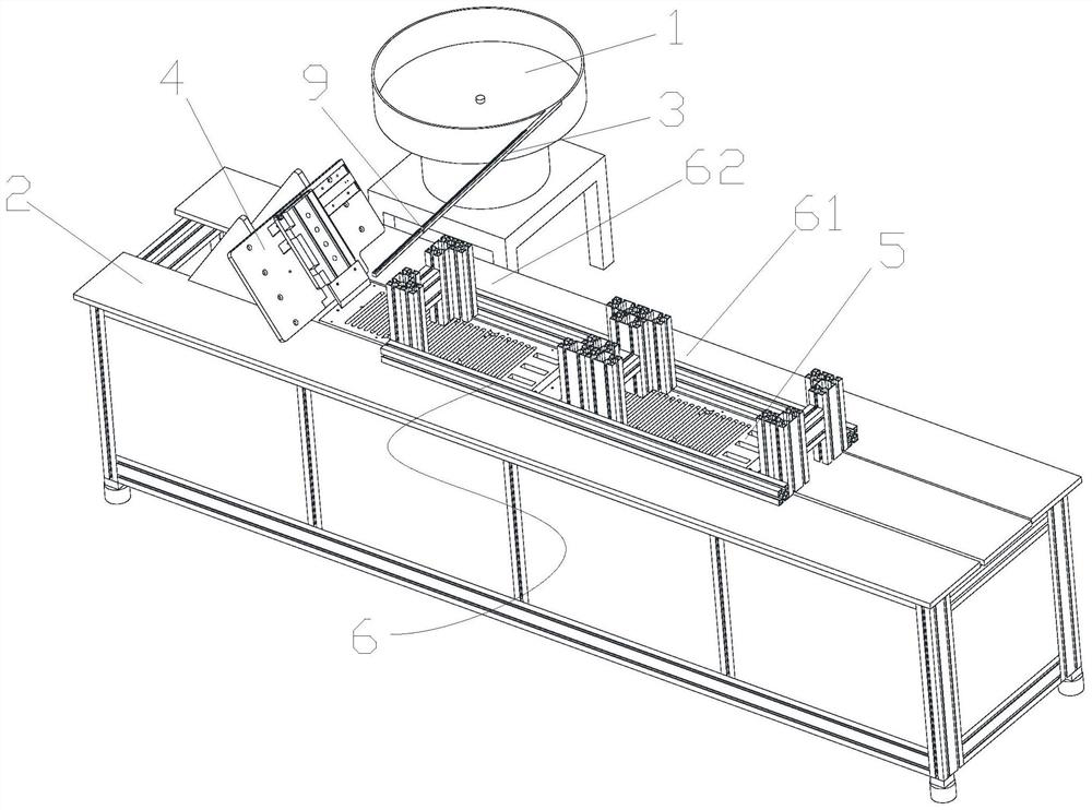
[0030] refer to figure 1As shown, a schematic structural diagram of a fully automatic arrangement and insertion device for saw chain cutter heads, a fully automatic arrangement and insertion device for saw chain cutter heads 8 and its working method, including the knives used for screening and can be arranged according to rules The vibrating plate 1 of the head 8, one end is connected to the discharge port of the vibrating plate 1, and the other end is erected on the cu...


PUM


Abstract

The invention provides full-automatic arranging and plug-in mounting equipment for saw chain tool bits and a working method of the full-automatic arranging and plug-in mounting equipment. The full-automatic arranging and plug-in mounting equipment comprises a vibration disc, a tool bit conveying channel, a plug-in mounting assembly, plug-in mounting plates and a plug-in mounting plate conveying channel, wherein the vibration disc is used for screening the tool bits and capable of arranging the tool bits according to rules, one end of the tool bit conveying channel is connected to a discharging port of the vibration disc, the other end of the tool bit conveying channel is erected on a machine frame, the plug-in mounting assembly is fixedly arranged at the upper portion of the machine frame and used for taking and plug-in mounting of the tool bits, the plug-in mounting plates are arranged on a plug-in mounting path of the plug-in mounting assembly and are used for plug-in mounting of the tool bits, and the plug-in mounting plate conveying channel is used for conveying and collecting the plug-in mounting plates. According to the full-automatic arranging and plug-in mounting equipment for the saw chain tool bits and the working method of the full-automatic arranging and plug-in mounting equipment, the automation degree is high, plug-in mounting is stable, not only can the tool bits be stably installed in the plug-in mounting plates, but also the situation that because an electromagnet plug-in mounting piece returns in the plug-in mounting process, the tool bits are brought out of a chute can be effectively avoided, and the production efficiency is greatly improved.

Description

technical field [0001] The invention belongs to the technical field of processing equipment for saw chain accessories, and in particular relates to a fully automatic arrangement and insertion equipment for saw chain cutter heads and a working method thereof. Background technique [0002] The saw chain is generally composed of four parts, including the cutter head, the middle guide tooth, the connecting piece and the rivet. The cutter head is divided into left and right cutter heads, and the connecting piece is divided into left and right connecting pieces. Some saw chains have some cushioning designs to reduce cutting rebound. These parts with cushioning features include cushioning guide teeth, cushioning connecting pieces, etc. Saw chain cutter heads generally need to be electroplated on the surface of the cutter head during processing to increase Its hardness prevents abrasion, and electroplating can improve the conductivity, smoothness, heat resistance and corrosion resis...

Claims


Application Information

Patent Timeline
Patent Type & Authority Applications(China)
IPC IPC(8): B23P21/00B23P19/00
CPCB23P19/001B23P21/004
Inventor 文小华
Owner 永康市科翰自动化设备厂
Why Eureka
Try Eureka