Vacuum electric scanning supersonic spray deposition electron beam additive manufacturing device

A technology of spray deposition and additive manufacturing, which is applied in the direction of manufacturing auxiliary devices, processing and manufacturing, additive processing, etc., can solve the problems of affecting the forming effect of parts, high cost of forming powder, and poor consistency of sintering quality, so as to avoid similar Casting defects, good consistency, and the effect of improving sintering efficiency

Pending Publication Date: 2021-05-11
重庆交通大学绿色航空技术研究院 +1
View PDF9 Cites 3 Cited by
  • Summary
  • Abstract
  • Description
  • Claims
  • Application Information

AI Technical Summary

Problems solved by technology

[0002] Additive manufacturing devices are also called 3D printers. Before each scanning process of existing additive manufacturing devices, the entire forming table needs to be filled with forming powder, and then the corresponding areas are sintered to form parts by layer-by-layer powder sintering. Secondary sintering needs to cover the entire forming table with forming powder, which is extremely inefficient and will lead to a large amount of waste of forming powder, a large amount of forming powder is used, and the cost of forming powder is relatively high. Too much, resulting in poor quality consistency of each layer of sintering, prone to typical casting defects, affecting the forming effect of parts

Method used


Image

  • Vacuum electric scanning supersonic spray deposition electron beam additive manufacturing device
  • Vacuum electric scanning supersonic spray deposition electron beam additive manufacturing device
  • Vacuum electric scanning supersonic spray deposition electron beam additive manufacturing device

Examples


Embodiment Construction

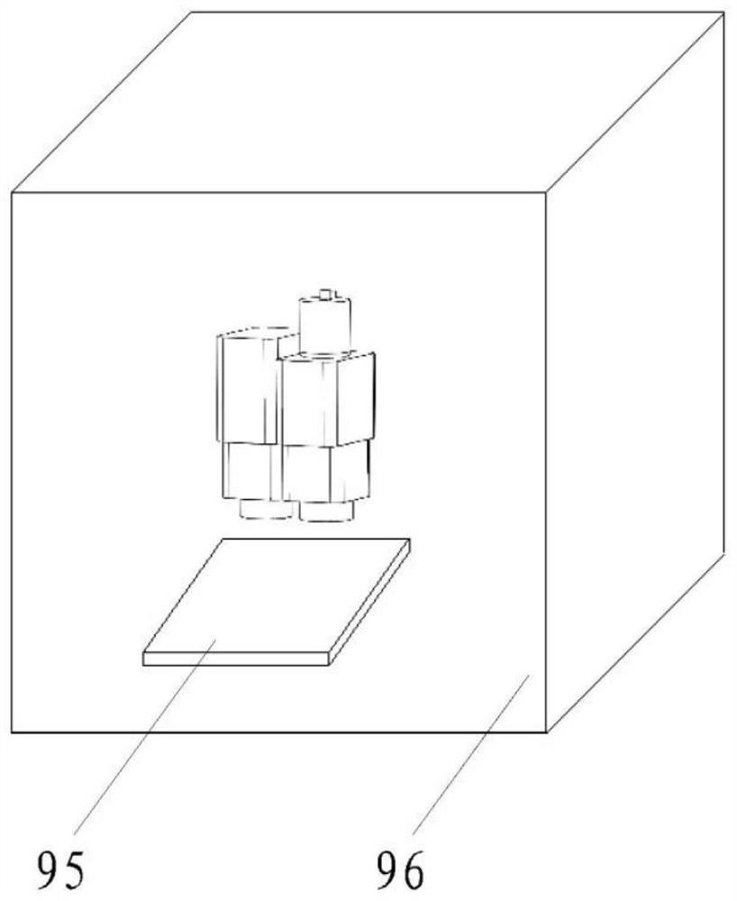
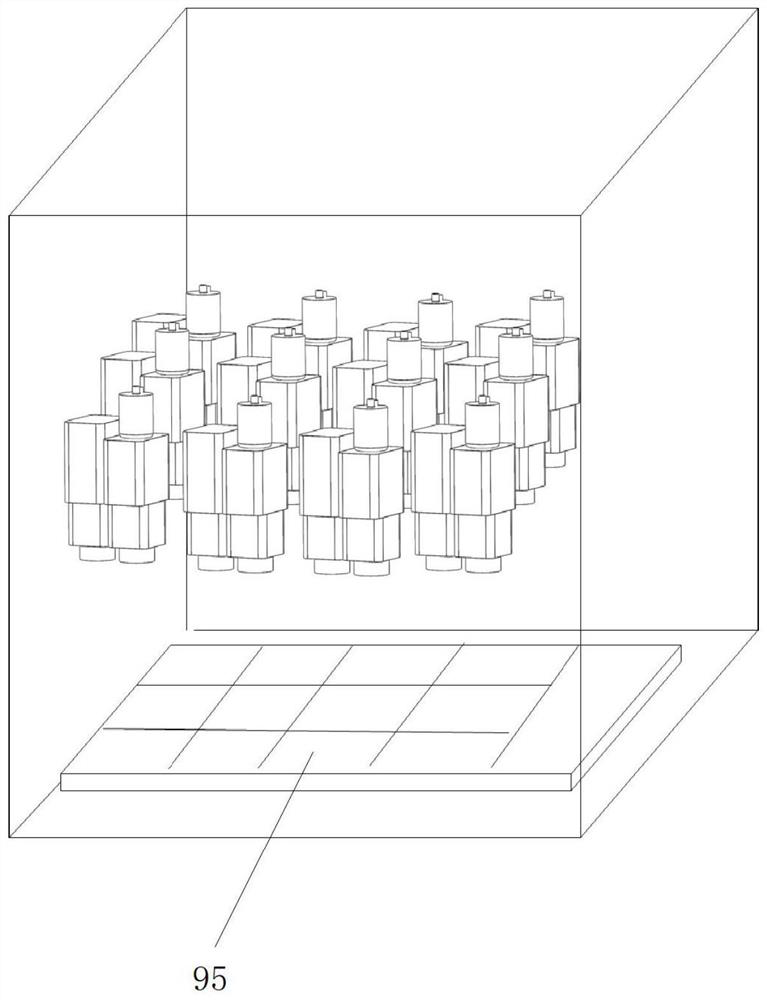
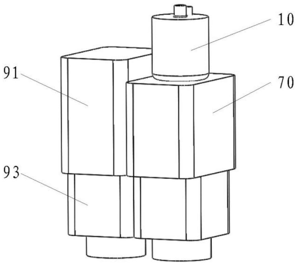
[0026]As shown, the vacuum electrical sweeping supersonic spray deposition of the present embodiment includes a forming table 94 and an electron beam spraying apparatus mounted above the table, the electron beam injection add material. The device includes a cold shower, a high energy electron beam emitter 91, and an electron beam control device, and the cold shirt injection direction is adjustable such that the discharged powder particle beam is scanned based on a component shape on the workbench, the electron beam control device mounted to high energy The electron beam emitter exits is used for the transmission direction of the electron beam, so that the powder particle bundle of the electron beam is ejected from the cold nozzle, and the powder particles are heated to form a melting state.

[0027]Combinefigure 1 withfigure 2 As shown, the table and the electron beam spray adding apparatus are mounted in the forming hood 95, wherein the electron beam spray adding means is mounted on t...


PUM


Abstract

The invention discloses a vacuum electric scanning supersonic spray deposition electron beam additive manufacturing device. The vacuum electric scanning supersonic spray deposition electron beam additive manufacturing device comprises a forming workbench and an electron beam spray additive device mounted above the workbench, wherein the electron beam spray additive device comprises a cold spraying head, a high-energy electron beam emitter and an electron beam control device. The spraying direction of the cold spraying head can be adjusted, so that sprayed powder particle beams can be scanned on the workbench based on shapes of parts; the electron beam control device is mounted at an emitting opening of the high-energy electron beam emitter and is used for controlling emitting directions of electron beams, so that the electron beams and the powder particle beams sprayed by the cold spraying head are collected at one point, and the surface of a substrate and the powder particles are heated to form a molten state. According to the device, the parts are formed by directionally spraying the powder and heating and sintering in real time; the powder is not needed to be laid layer by layer and sintered; the forming efficiency is greatly improved; the waste of the powder is avoided; the forming cost is reduced; the forming quality consistency is good; the forming quality is improved; the part sintering process is simplified; and the sintering efficiency is improved.

Description

Technical field[0001]The present invention relates to the field of surface ejecting techniques, and in particular, to a vacuum electrical sweeping supersonic injection deposition electron beam additive manufacturing apparatus.Background technique[0002]The additive manufacturing apparatus is also referred to as a 3D printer, and the existing additive manufacturing apparatus needs to fill the entire forming table, and then sinrate the corresponding region, and form a part by layer by layer by layer. The sintering needs to cover the entire forming work table, which is extremely low, and can cause a large amount of molding powder to waste, the molded powder is large, the molded powder is high, and the uncontrollable factor of the powder is higher. Many, resulting in poor quality consistency per layer, it is easy to show typical casting defects, affecting the forming effect of components.[0003]Therefore, there is a need for a vacuum electrical sweeping supersonic injection deposition ele...

Claims


Application Information

Patent Timeline
Patent Type & Authority Applications(China)
IPC IPC(8): B29C64/153B29C64/20B29C64/393B33Y10/00B33Y30/00B33Y50/02
CPCB29C64/153B29C64/20B29C64/393B33Y10/00B33Y30/00B33Y50/02
Inventor 柳平延黎周留成黄忠桓安志斌贾文铜苗卓广刘东亮黄萌林敏
Owner 重庆交通大学绿色航空技术研究院
Why Eureka
Try Eureka