High-power laser diode horizontal linear array pumped solid laser cavity

A laser diode and solid-state laser technology, applied in the field of solid-state laser cavity, can solve the problems of difficult sintering process, limited pump power, complicated system structure, etc. Effect

Active Publication Date: 2012-04-18
SUZHOU GUANGGE EQUIP
View PDF2 Cites 0 Cited by
  • Summary
  • Abstract
  • Description
  • Claims
  • Application Information

AI Technical Summary

Problems solved by technology

Using the above method, the light conversion efficiency is low, and the structure is complicated, the cost is high, and it is not conducive to mass production
[0003] The new pumping scheme tries to overcome the shortcomings of the traditional scheme. The Chinese patent with the patent publication number of CN1417906 proposes an integrated ring-shaped high-power laser diode bar pump cavity. The cavity is composed of multiple high-power laser diode bars and A plurality of arc-shaped electrodes are installed in a circle on the inner surface of the insulating ring. The arc-shaped electrodes constitute a closed pump chamber whose inner surface is a highly reflective surface. The pump light that is not fully absorbed passes through the inner surface of the arc-shaped electrodes. The secondary reflection is finally absorbed by the crystal rod, so as to achieve high absorption efficiency. This kind of pump cavity does not need a complicated optical coupling system, and has the characteristics of novel structure and high efficiency. However, the laser needs to be sintered with the arc electrode, which is different from The traditional square heat sink increases the difficulty of sintering, and generally only one bar can be sintered between adjacent arc-shaped electrodes, and generally only 3-5 bars can be sintered between multiple arc-shaped electrodes in a circle, so For higher power applications, multiple modules need to be connected in series, which increases the complexity of the system
Chinese patent CN1681171 proposes a kind of eccentric injection of pump light, through the multiple diffuse reflections of the inner wall of the pump cavity to uniformly pump the pump cavity of the laser crystal rod. Complex optical coupling system, this structure improves the uniformity of pumping, thereby reducing the thermal stress on the crystal rod, improving the beam quality and pumping efficiency, but due to the large absorption loss of the slit, only a single slit, so the pump module can only use a single linear array, resulting in the limitation of the injected pump light power, if the number of slits is increased, the loss will increase
In short, the new scheme still has disadvantages such as difficult sintering process, complex system composition, or limited pump power.

Method used


Image

  • High-power laser diode horizontal linear array pumped solid laser cavity
  • High-power laser diode horizontal linear array pumped solid laser cavity
  • High-power laser diode horizontal linear array pumped solid laser cavity

Examples


Embodiment 1

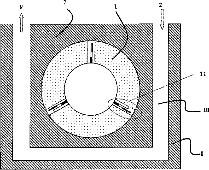
[0016] Example 1: see figure 1 As shown, it is a schematic cross-sectional view of a high-power laser diode horizontal linear array pumped solid laser cavity structure provided by this embodiment. in figure 1 Among them, three horizontal linear arrays of laser diodes 11 are respectively connected with three arc-shaped heat sinks 1 to form a circle. The arc-shaped heat sinks form a cylindrical surface with a highly reflective inner surface, and the cylindrical surface is a pumping cavity. The inner surface of the arc heat sink can be polished and then plated with gold to form a highly reflective surface or coated with a highly reflective dielectric film.

[0017] The arc-shaped heat sink 1 is placed in the through hole of the inner wall 7 of the water-cooled heat sink. A cooling water channel 10 is formed between the inner wall 7 of the water-cooled heat sink and the outer wall 8 of the water-cooled heat sink for heat dissipation. The cooling water flows into the inlet 2 of the coo...


PUM


Abstract

The invention discloses a high-power laser diode horizontal linear array pumped solid laser cavity which comprises arc-shaped heat sinks, a water-cooling heat sink inner wall, a cooling water channel, a water-cooling heat sink outer wall and laser diode horizontal linear arrays, wherein the laser diode horizontal linear arrays (11) and the arc-shaped heat sinks (1) in same number are arranged at intervals for enclosing a circle; the inner surface of each arc-shaped heat sink is provided with a high-reflection cylindrical pumping cavity; the arc-shaped heat sinks are arranged in through holes of the water-cooling heat sink inner wall (7); and the cooling water channel (10) is formed between the periphery of the through holes and the water-cooling heat sink outer wall (8). The technical scheme provided by the invention has the characteristics of simple preparation process, high integrated level, easy modularized mass production and high efficiency.

Description

Technical field [0001] The invention relates to a solid laser cavity, in particular to a high-power laser diode horizontal linear array pumped solid laser cavity. Background technique [0002] In the traditional high-power laser diode pumped solid-state laser cavity, because the divergence angle of the high-power semiconductor laser is relatively large, generally 40×10 degrees, it is possible that part of the pump light is irradiated outside the crystal rod. If it is not absorbed by the crystal, or even if it is completely irradiated to the crystal, the absorption is not complete at one time, and part of the light passes through the crystal. This requires the light that is transmitted or not absorbed by the crystal to be reflected back to the crystal again. The usual method is to install a collimating lens to make the divergence angle of the semiconductor laser become very small. At the same time, use a quartz tube, most of the surface is plated with 808nm high-reflection film, ...

Claims


Application Information

Patent Timeline
Patent Type & Authority Patents(China)
IPC IPC(8): H01S3/0941H01S3/042
Inventor 陈志标
Owner SUZHOU GUANGGE EQUIP
Why Eureka
Try Eureka