Sorting method of connecting rod balance wheel sorting machine

A sorter and connecting rod technology, which is applied in the field of logistics and warehousing, can solve the problems of complex structure of transmission mechanism and swing drive mechanism, large consumption of swing drive force, wrong sorting results, etc.

Inactive Publication Date: 2021-05-11
QINGDAO KENGIC AUTOMATION EQUIP CO LTD
View PDF3 Cites 2 Cited by
  • Summary
  • Abstract
  • Description
  • Claims
  • Application Information

AI Technical Summary

Problems solved by technology

[0004] The disadvantages of the above-mentioned prior application are as follows: first, due to the adoption of two layers of intersecting link mechanisms, that is, the first link is driven in the conveying direction, and the second link is driven perpendicular to the conveying direction. The swing driving force transmitted by the first stage consumes a lot during the transmission process, and it needs to be equipped with a motor with a large output power, which not only increases the energy consumption but also makes noise; , the gap between the first connecting rod and the second connecting rod increases due to wear and tear, resulting in a deviation in force transmission, which directly affects the accuracy of the swing direction and angle, and even wrong sorting results occur, which is necessary for subsequent equipment maintenance. Third, the structure of the transmission mechanism and the swing drive mechanism is still relatively complicated, which is not conducive to reducing the requirements for component processing and equipment debugging accuracy
Under the complex working environment of the existing sorting machine, the sealing requirements for the structure of the balance wheel are still high, and the later maintenance and maintenance are still cumbersome

Method used


Image

  • Sorting method of connecting rod balance wheel sorting machine
  • Sorting method of connecting rod balance wheel sorting machine
  • Sorting method of connecting rod balance wheel sorting machine

Examples


Embodiment 1

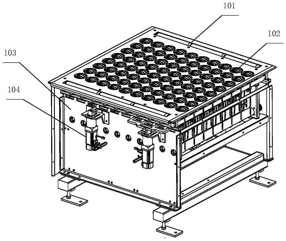
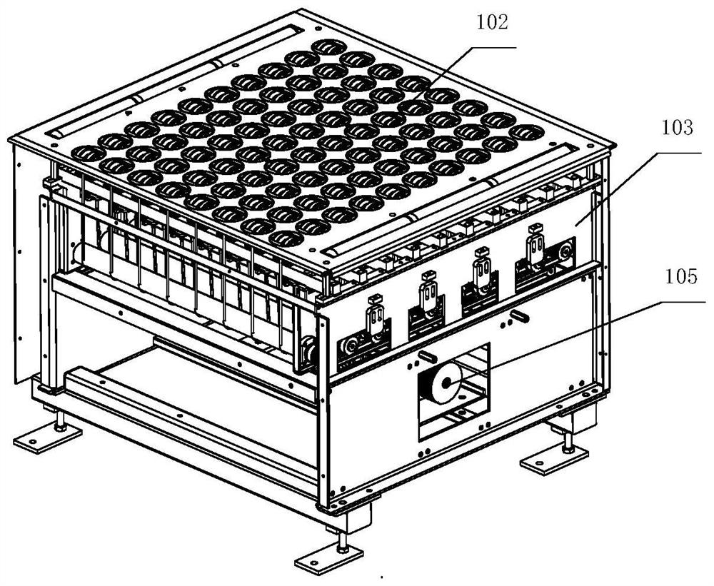
[0033] Embodiment 1, as shown in the above drawings, the sorting method of the link balance wheel sorter described in this application is applied. The link balance wheel sorter includes a shell module 101, a balance wheel module 102, a machine Frame module 103, swing power unit 104 and conveying power unit 105.

[0034] Wherein, the balance wheel module 102, the swing power unit 104 and the transmission power unit 105 are respectively installed on the frame module 103;

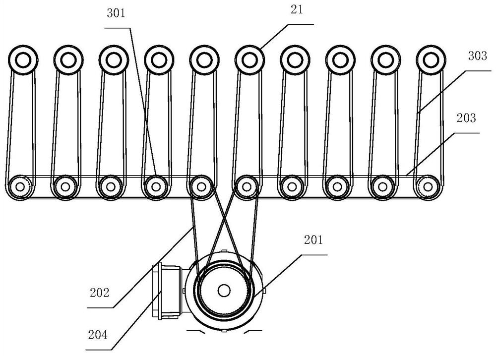
[0035] 80 sets of balance wheel modules are distributed in rows and columns, and the swing power unit 104 includes a set of reversing levers 403 located below the 8 sets of balance wheel modules 102 in each row. Between the reversing levers 403 and each balance wheel module A steering rod 404 is connected between the balance wheel bracket shaft 23 of 102, and the steering rod 404 is a U-shaped connecting rod structure;

[0036] There are 8 groups of balance wheel modules 102 in each row, and the balance wheel...


PUM


Abstract

The invention discloses a sorting method of a connecting rod balance wheel sorting machine. A swing driving mechanism is correspondingly improved to be in a tiled transmission mode, that is, rotation driving force is converted into balance wheel synchronous swing through single-layer linear transmission of the swing driving mechanism, and the purposes of effectively reducing transmission force loss and transmission noise, improving the synchronous performance of swing control, simplifying the structure, and reducing the later maintenance workload are achieved. The swing control process of a swing power unit is as follows: 1) servo motors drive steering blocks to rotate clockwise or anticlockwise by taking motor output shafts as centers; (2) the steering blocks push multiple sets of steering rods to synchronously and horizontally move in the row or column direction; (3) the steering rods are driven by reversing rods to rotate clockwise or anticlockwise with the connecting points of the steering rods and balance wheel support shafts as the centers; and (4) a whole balance wheel module and the steering rods synchronously rotate, and the conveying direction of goods borne on balance wheels is correspondingly changed.

Description

technical field [0001] The invention is an improved sorting method of a connecting rod balance wheel sorter, which is a supplementary improvement to the electric connecting rod balance wheel sorter and its swing control method proposed by the applicant in the prior application CN201910895675X, and belongs to logistics Warehousing field. Background technique [0002] At present, in the process of logistics warehousing and transportation, the equipment used for sorting goods usually includes a balance wheel sorter. The balance wheel sorter controls the steering according to the different classifications or conveying directions of the goods. The balance wheel is used to rotate and transport the goods to different outlets through the steering drive of the swing mechanism, so as to realize the sorting function. [0003] The existing public sorter adopts the link type transmission mechanism, which cancels the transmission mode of the traditional structure of the rack and pinion. ...

Claims


Application Information

Patent Timeline
Patent Type & Authority Applications(China)
IPC IPC(8): B65G13/07B65G13/11B65G13/00B65G47/22B07C3/02
CPCB65G13/07B65G13/11B65G13/00B65G47/22B07C3/02
Inventor 孙旭唐兵孙炜凯
Owner QINGDAO KENGIC AUTOMATION EQUIP CO LTD
Why Eureka
Try Eureka