
Filter circuit, automatic tuning circuit, filter adjusting circuit and adjusting method

A filter and low-pass filter technology, applied in the field of filters, can solve the problems of complex filter structure, high power consumption, large chip area, etc.

Pending Publication Date: 2021-05-11
江苏集萃智能集成电路设计技术研究所有限公司
View PDF0 Cites 0 Cited by
  • Summary
  • Abstract
  • Description
  • Claims
  • Application Information

AI Technical Summary

Problems solved by technology

[0004] Aiming at the problems in the prior art that the filter structure is complex, the included resistors and capacitors occupy a large chip area, and it is difficult to obtain a large bandwidth due to the limitation of power consumption, or it is easy to generate large power consumption, the present invention provides a filter The device circuit structure and its method, its structural design is simple and reasonable, can reduce the area occupied by the chip, and has a multi-channel selection function, which can meet the requirements of high broadband gain and low power consumption at the same time

Method used


Image

  • Filter circuit, automatic tuning circuit, filter adjusting circuit and adjusting method
  • Filter circuit, automatic tuning circuit, filter adjusting circuit and adjusting method
  • Filter circuit, automatic tuning circuit, filter adjusting circuit and adjusting method

Examples


Embodiment Construction

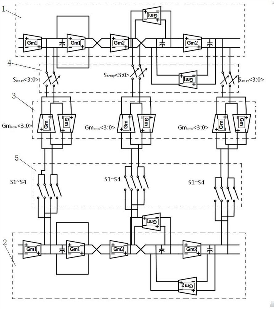
[0070] See figure 2 , a filter circuit, the filter is a third-order reconfigurable gm-c complex bandpass filter, the filter circuit includes an I channel 1, a Q channel 2, a cross-coupling module 3, and a switch module, The I channel 1 and the Q channel 2 are respectively used to filter the differential signal. The switch module includes a linkage switch 4 and a sorting switch 5. The I channel 1 is connected to the cross-coupling module 3 through the linkage switch 4, and the Q channel 2 passes through The sorting switch 4 is connected to the cross-coupling module 3; the linkage switch 4 is used to control the on-off of the cross-coupling module 3, the sorting switch 5 is used to control the coupling direction of the cross-coupling module 3, and the center of the filter is controlled by the linkage switch 4. Frequency, through the sorting switch 5 to control the positive and negative of the center frequency.

[0071] The I channel 1 and the Q channel 2 respectively include a...


PUM


Abstract

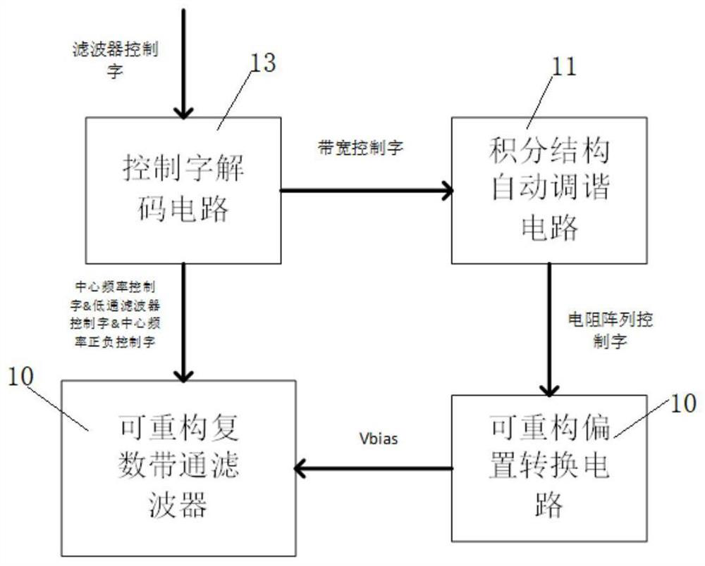
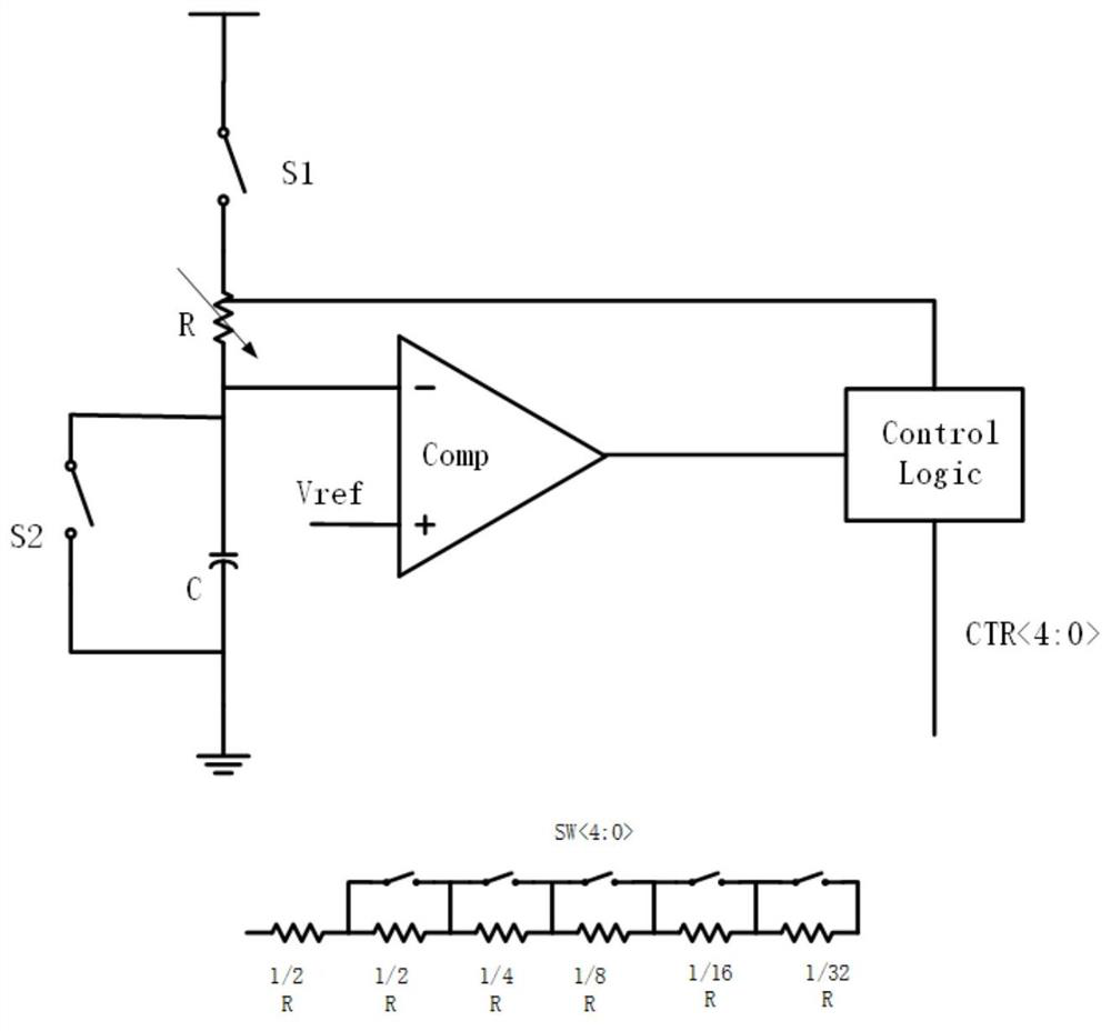
The invention discloses a filter circuit, an automatic tuning circuit, a filter adjusting circuit and an adjusting method. The filter circuit is simple and reasonable in structural design, can reduce the occupied area of a chip, has a multi-channel selection function, and can meet the requirements of high broadband gain, low power consumption and the like at the same time. The filter circuit structure comprises a third-order reconfigurable gm-c complex band-pass filter circuit, a reconfigurable bias circuit structure, an automatic tuning circuit structure and an integral structure, wherein the automatic tuning circuit is connected with the third-order reconfigurable gm-c complex band-pass filter through the reconfigurable bias circuit; the integral structure automatic tuning circuit is used for generating a resistor array control word to control the reconfigurable biasing circuit, and the reconfigurable biasing circuit is used for generating bias voltage used by the third-order reconfigurable gm-c complex band-pass filter. The invention further discloses a method for adjusting the center frequency and bandwidth of a third-order reconfigurable gm-c complex band-pass filter by applying a reconfigurable biasing circuit structure and an automatic tuning circuit.

Description

technical field [0001] The invention relates to the technical field of filters, in particular to a filter circuit, an automatic tuning circuit, a filter adjusting circuit and an adjusting method. Background technique [0002] At present, in the radio frequency transceiver system, commonly used radio frequency transceiver structures mainly include zero-IF structure and low-IF structure. There is no image signal in the zero-IF structure receiver, but there are 1 / f noise and DC offset and other problems. The IF filter is a low-pass filter with simple circuit and low power consumption. Therefore, low-IF is usually used in narrowband communication. structure, the intermediate frequency filter can filter out the image interference signal after mixing in the receiving system, and at the same time it needs to perform channel selection in multi-channel standards, so a reconfigurable complex bandpass filter with channel selection function can be used in the low intermediate frequency ...

Claims


Application Information

Patent Timeline
IPC IPC(8): H03H11/04
CPCH03H11/04
Inventor 卢丛远樊晓华杨中蔡青松郭晓旭
Owner 江苏集萃智能集成电路设计技术研究所有限公司
Learn More