Snake venom serum extraction device
An extraction device and serum technology, which is applied in the field of snake venom serum extraction devices, can solve problems such as low efficiency, hemolysis, and cell wall damage, and achieve the effects of easy use, strong applicability, and improved efficiency
- Summary
- Abstract
- Description
- Claims
- Application Information
AI Technical Summary
Problems solved by technology
Method used
Image
Examples
Embodiment 1
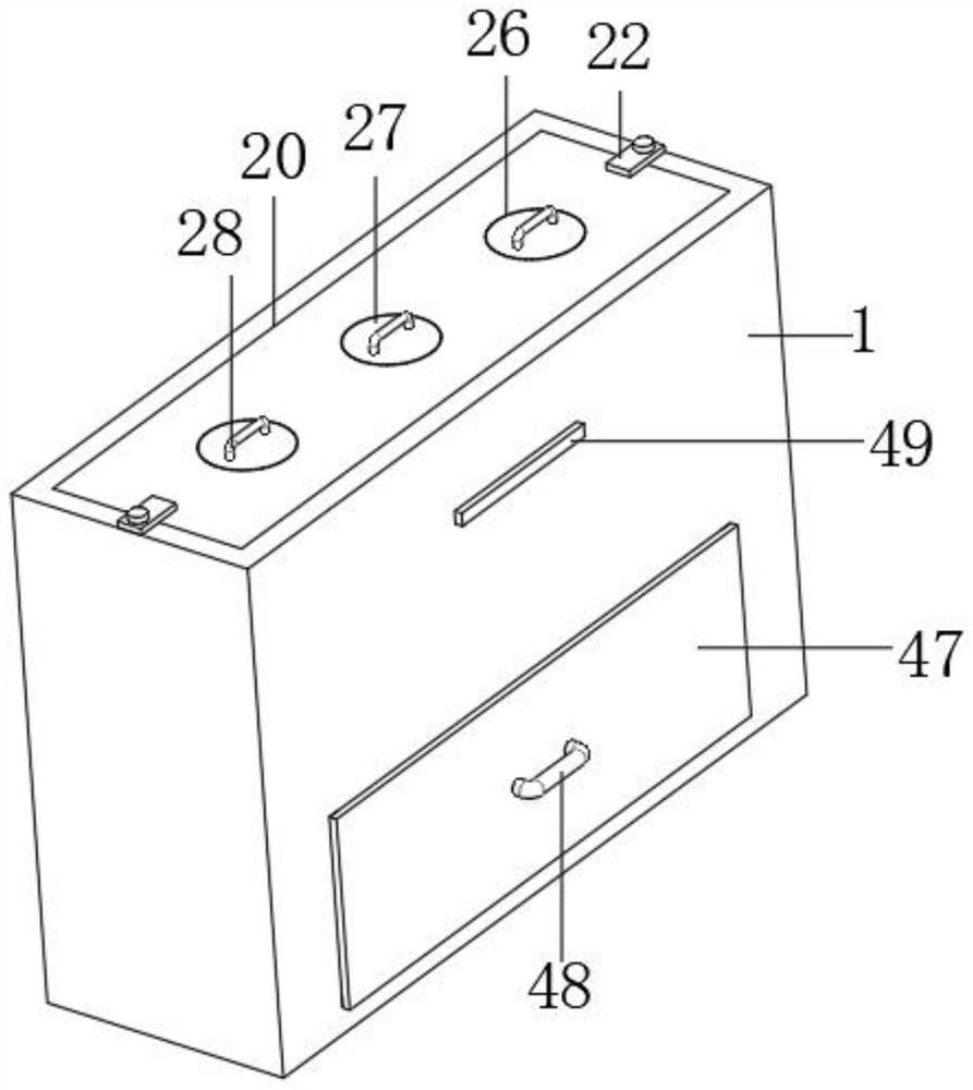
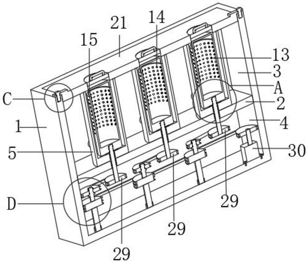
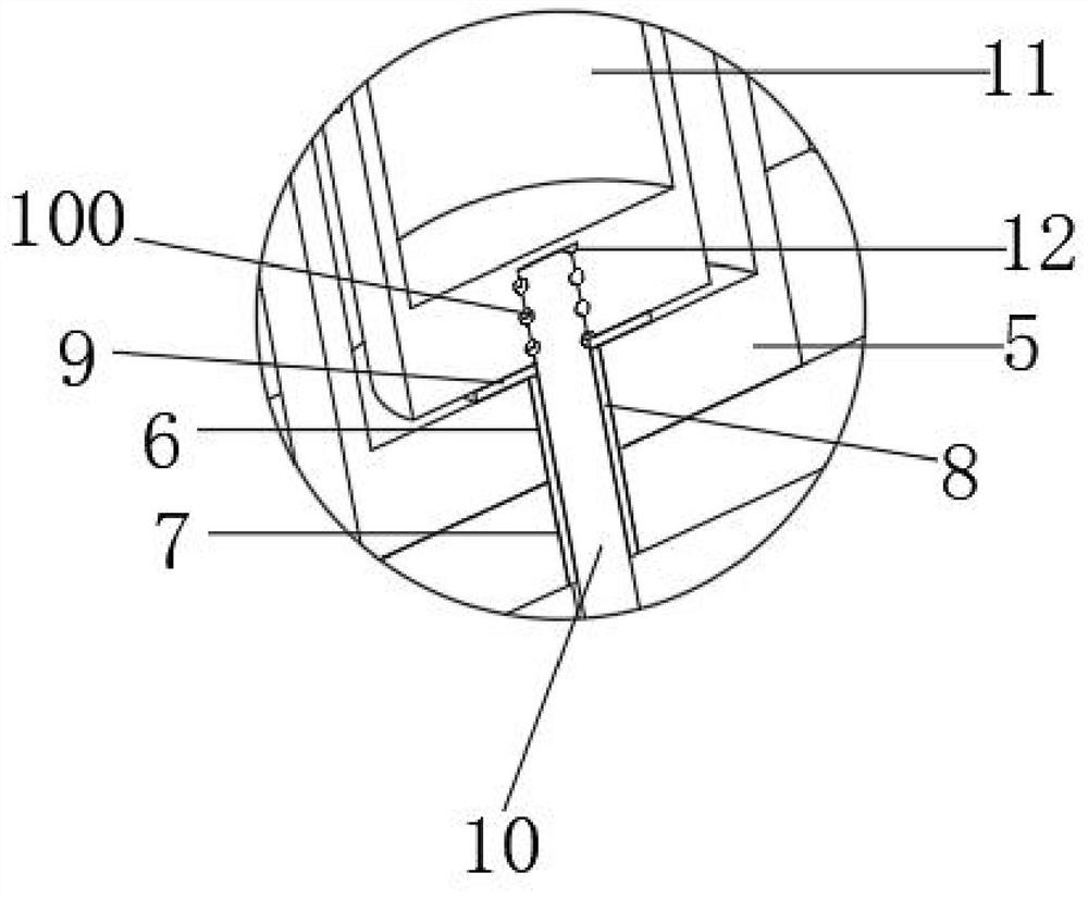
[0039] Such as figure 1 , figure 2 and image 3 as shown,
[0040] A device for extracting snake venom serum, comprising a centrifuge box 1, a partition 2 is fixed inside the centrifuge box 1, and the partition 2 is arranged at the lower part of the inner cavity center of the centrifuge box 1, and the partition 2 divides the centrifuge box 1 into an upper centrifugal area 3 and the lower power zone 4, centrifugal components are arranged inside the centrifugal zone 3, three sets of centrifugal components are arranged at the center of the top of the partition plate 2 at equal intervals, the centrifugal components include an outer cylinder 5, a first through hole 6, a second through hole Hole 7, sealed bearing 8, stop ring 9, rotating rod 10, connecting thread 100, inner cylinder 11, connecting screw hole 12, centrifugal hole 13, blood separation diaphragm 14 and inverted U-shaped handle 15;
[0041] The outer cylinder 5 is fixed at the top center of the partition 2, the firs...
Embodiment 2
[0043] Embodiment 2 is a further improvement to Embodiment 1:
[0044] Such as figure 2 , Figure 7 and Figure 8 As shown, a power assembly is arranged inside the power area 4, and the power assembly includes a motor 30, an output shaft 31, a main pulley 32, a double-groove pulley 33, a support rod 34, a rotating bearing 35, a transmission belt 36, a transmission rod 37, and a transmission thread 38, limit ring 39, transmission pulley 40, transmission screw hole 41, limit nut 42 and transmission belt 43;
[0045] The motor 30 is arranged on one side of the bottom end of the power zone 4, the motor 30 is screwed to the bottom end of the power zone 4, the main pulley 32 is arranged on the bottom end of the output shaft 31, the rotating bearings 35 are arranged at the bottom end of the power zone 4 at equal intervals, and the support rod 34 Rotate in the rotating bearing 35, the double-groove pulley 33 is fixed on the support bar 34 tops, the vertical center line of the doub...
Embodiment 3
[0047] Embodiment 3 is a further improvement to embodiment 2:
[0048] Such as figure 2 , Figure 4 , Figure 5 , Figure 6 , Figure 9 and Figure 10 As shown, a liquid outlet 16 is provided on the side wall of the outer cylinder 5, and the level at the bottom of the liquid outlet 16 is lower than that at the bottom of the inner cavity of the outer cylinder 5, and a through hole 17 is provided on the side wall of the centrifugal box 1. A liquid outlet pipe 18 is installed inside the through hole 17 and the liquid outlet 16, a valve 19 is arranged on the side wall of the liquid outlet pipe 18, an open groove 20 is opened in the center of the top of the centrifugal area 3, and a cover plate 21 is installed in the open groove 20, Both sides of the top center of the cover plate 21 are fixed with a connecting plate 22, the top of the connecting plate 22 is provided with a through screw hole 23, the top of the centrifugal box 1 is provided with a matching screw hole 24, and t...
PUM
 Abstract
Description
Claims
Application Information
 - R&D
- Intellectual Property
- Life Sciences
- Materials
- Tech Scout
- Unparalleled Data Quality
- Higher Quality Content
- 60% Fewer Hallucinations
Browse by: Latest US Patents, China's latest patents, Technical Efficacy Thesaurus, Application Domain, Technology Topic, Popular Technical Reports.
© 2025 PatSnap. All rights reserved.Legal|Privacy policy|Modern Slavery Act Transparency Statement|Sitemap|About US| Contact US: help@patsnap.com


