
Lithium ion battery steel shell and method for improving liquid injection efficiency of steel shell

A lithium-ion battery and steel case technology, applied in the field of lithium-ion battery steel case and improving the liquid injection efficiency of the steel case, can solve the problems such as the inability to discharge the gas, and achieve the advantages of avoiding electrolyte leakage, increasing liquid injection efficiency, and convenient operation Effect

Active Publication Date: 2021-05-14
SINOWATT DONGGUAN
View PDF11 Cites 0 Cited by
  • Summary
  • Abstract
  • Description
  • Claims
  • Application Information

AI Technical Summary

Problems solved by technology

[0006] The object of the present invention is to provide a lithium ion battery steel case, which can be exhausted in real time during liquid injection through the exhaust mechanism provided, thereby increasing the liquid injection efficiency. The pressure of the air can be exhausted to improve the gas output efficiency, aiming to solve the problem of the introduction of moisture caused by the low efficiency of liquid injection in the prior art. The gas generated in the subsequent formation cannot be discharged, which will become a constraint for high-nickel positive electrode materials and silicon negative electrode materials. A major pain point in the rapid promotion and application of cylindrical batteries

Method used


Image

  • Lithium ion battery steel shell and method for improving liquid injection efficiency of steel shell
  • Lithium ion battery steel shell and method for improving liquid injection efficiency of steel shell
  • Lithium ion battery steel shell and method for improving liquid injection efficiency of steel shell

Examples


Embodiment Construction

[0030] In order to make the object, technical solution and advantages of the present invention clearer, the present invention will be further described in detail below in conjunction with the accompanying drawings and embodiments. It should be understood that the specific embodiments described here are only used to explain the present invention, not to limit the present invention.

[0031] The implementation of the present invention will be described in detail below in conjunction with specific embodiments.

[0032] In the drawings of this embodiment, the same or similar symbols correspond to the same or similar components; The indicated orientation or positional relationship is based on the orientation or positional relationship shown in the drawings, and is only for the convenience of describing the present invention and simplifying the description, rather than indicating or implying that the referred device or element must have a specific orientation, or in a specific orien...


PUM


Abstract

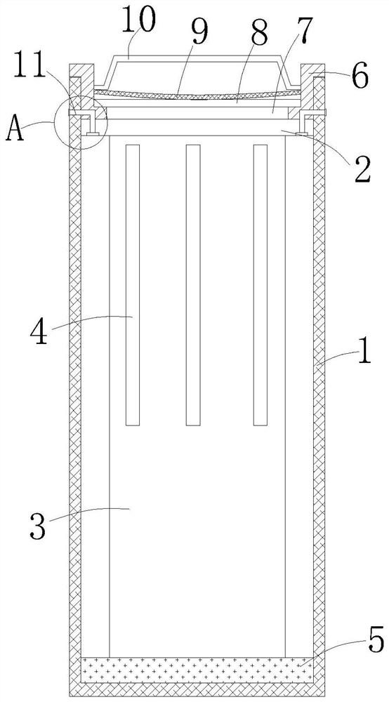
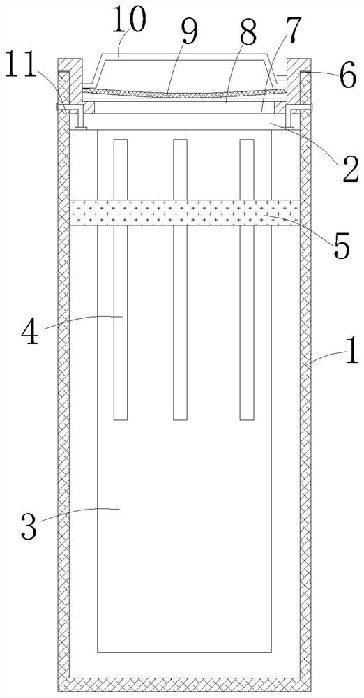
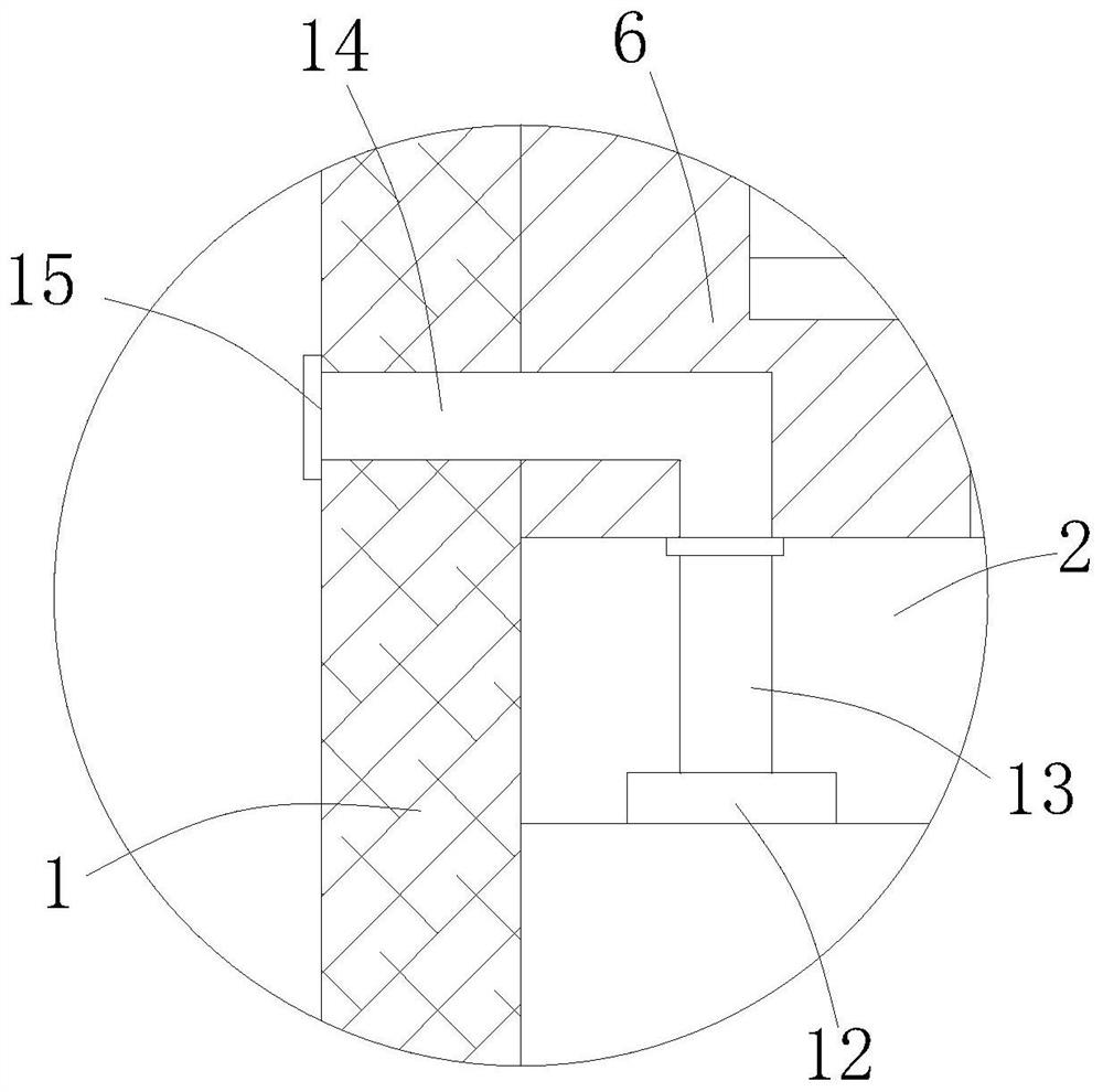
The invention relates to the technical field of lithium ion batteries, and discloses a lithium ion battery steel shell and a method for improving the liquid injection efficiency of the steel shell. The lithium ion battery steel shell comprises a steel shell body, a fixing ring is fixed to the side wall of the upper portion in the steel shell body, a connecting cover is arranged on the lower portion of the fixing ring, the lower portion of the connecting cover extends to the lower portion in the steel shell body, and a plurality of ventilation openings are evenly formed in the outer wall of the connecting cover. The outer wall of the lower portion of the connecting cover is sleeved with a floating pad, a sealing ring is arranged on the outer wall of the through opening of the steel shell body, an exhaust mechanism is arranged in the sealing ring, one end of the exhaust mechanism is connected with the interior of the steel shell body, and the other end of the exhaust mechanism sequentially penetrates through the fixing ring, the sealing ring and the side wall of the steel shell body to be communicated with the outside. According to the invention, air can be exhausted in real time during liquid injection through the arranged exhaust mechanism, meanwhile, the arranged floating pad can move along with the liquid injection height, pressure of air on the upper portion is exhausted, and the air outlet efficiency is improved.

Description

technical field [0001] The patent of the present invention relates to the technical field of lithium-ion batteries, in particular, to a lithium-ion battery steel case and a method for improving the liquid injection efficiency of the steel case. Background technique [0002] The improvement of energy density has always been one of the directions pursued by lithium-ion battery practitioners. High-nickel cathode materials and silicon anode materials are the only way to increase the energy density of lithium-ion batteries. Due to the characteristics of the positive and high nickel material and the silicon negative material, the compaction thickness of the positive and negative electrodes is at a relatively thick level, resulting in a larger size of the battery cell and a smaller gap between the steel shell and difficult liquid injection. , reducing production efficiency. And the longer the liquid injection time, the easier it is to introduce moisture. In addition to the gas pr...

Claims


Application Information

Patent Timeline
Patent Type & Authority Applications(China)
IPC IPC(8): H01M50/367H01M50/107H01M50/636H01M50/609H01M10/0525
CPCH01M10/0525Y02E60/10
Inventor 郭密孙世敏王珍珍陈述林赵川吴国强万里鹏徐鲲曾素琼兰水静
Owner SINOWATT DONGGUAN
Learn More