New method for additive preparation of metal product

A new method, metal technology, applied in the field of additive manufacturing of metal products, can solve the problems of inconspicuous strengthening, limited laser penetration ability, and lack of actual operation functions.

Inactive Publication Date: 2021-05-18
CENT SOUTH UNIV
View PDF7 Cites 4 Cited by
  • Summary
  • Abstract
  • Description
  • Claims
  • Application Information

AI Technical Summary

Problems solved by technology

[0004] 1. Appearance parts and scale display parts only have display functions and do not have actual operation functions
[0005] 2. Non-load-bearing parts, such as metal jewelry, can be used but not load-bearing
[0011] At present, some people use laser shock peening technology (laser peening technology) to strengthen metal 3D printing parts after treatment. However, due to the limited laser penetratio...

Method used


Image

  • New method for additive preparation of metal product
  • New method for additive preparation of metal product
  • New method for additive preparation of metal product

Examples


Embodiment 1

[0042] Embodiment 1, the present embodiment prepares die cutter according to the method provided by the present invention, and concrete steps are as follows:

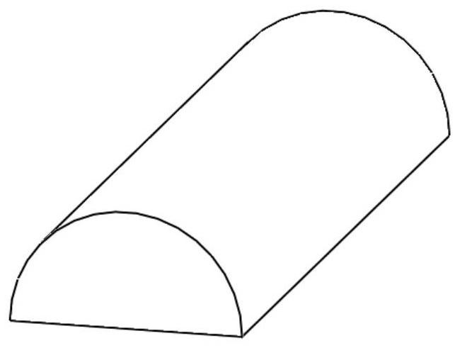
[0043] Step 1. Draw a 3D model:

[0044] According to the two-dimensional drawing of the cutting die, use drawing software such as Solidworks to draw the corresponding three-dimensional model, and generate a file in stl format, such as figure 1 shown;

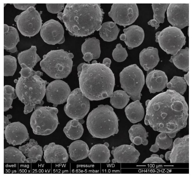
[0045] Step 2, material selection:

[0046] According to the cutting material of the tool, select the corresponding material. In this example, GH4169 spherical powder is selected, the particle size is 75-150 μm, and the raw material is as microscopic as figure 2 As shown, the base material is 316L stainless steel, and the base thickness is 10mm.

[0047] Step 3, parameter setting:

[0048] Import the stl file into the slicing software, set the laser power to 600W, the scanning speed to 600 mm / min, the powder feeding rate to 0.3r / min, the layer thickness to 0.3mm, an...

Embodiment 2

[0060] The present embodiment prepares a kind of knife die product, and preparation process comprises the following steps:

[0061] Step 1. Draw a 3D model:

[0062] According to the two-dimensional drawing of the cutting die, use drawing software such as Solidworks to draw the corresponding three-dimensional model, and generate a file in stl format, such as Figure 9 shown;

[0063] Step 2, material selection:

[0064] According to the cutting material of the tool, select the corresponding material. In this example, 420 stainless steel spherical powder is selected, the particle size is 75-150 μm, and the raw material is as microscopic as Figure 10 As shown, the base material is 316L stainless steel, and the base thickness is 10mm;

[0065] Step 3, parameter setting:

[0066] Import the stl file into the slicing software, set the laser power to 450W, the scanning speed to 400 mm / min, the powder feeding rate to 0.2r / min, and the layer thickness to 0.2mm. Impact strengthen...


PUM

PropertyMeasurementUnit
Spot diameteraaaaaaaaaa
Thicknessaaaaaaaaaa

Abstract

The invention discloses a novel method for additive preparation of a metal product. The metal product is prepared by adopting a mode of combining metal 3D printing and laser peening, laser peening treatment is introduced in the printing forming process, and the method comprises the following steps that according to a product design drawing, drawing software is used for drawing the design drawing into a three-dimensional model; the drawn three-dimensional model is substituted into slicing software, printing parameters are set, and a corresponding G code is generated; and the generated G code is substituted into an upper computer, and metal 3D printing forming equipment is controlled to carry out product printing forming. Laser shock peening is carried out under the state that each forming layer is not completely solidified, or laser shock peening is carried out on a metal cladding body while printing forming is carried out, so that the organization structure of the metal is more compact, crystal grains are further refined, the problems of holes, cracks, surface spheroidization, coarse crystal grains and the like in a formed part are eliminated, a high-strength and high-hardness metal product with excellent performance is obtained, and a 3D metal printing main force bearing part can enter a substantive use stage.

Description

technical field [0001] The invention belongs to the field of metal additive manufacturing and relates to a new method for additively preparing metal products. Background technique [0002] Additive manufacturing technology, also known as 3D printing technology, adopts the principle of discrete accumulation. According to the three-dimensional digital model of the parts to be manufactured, it is layered according to a certain thickness, and the sheets are continuously processed in a planar manner, and finally the "sheets" are superimposed to become the final product. 3D components. Compared with other traditional manufacturing technologies, it has the characteristics of new molding concepts, strong technical adaptability, and the realization of "function-first design". [0003] At present, 3D printing products are mainly divided into the following five types: [0004] 1. Appearance parts and scale display parts only have the function of display and do not have the function o...

Claims


Application Information

Patent Timeline
IPC IPC(8): B22F10/28B22F10/50B22F10/60B33Y10/00B33Y40/20
CPCB22F3/24B33Y10/00B33Y40/20
Inventor 刘军王臻
Owner CENT SOUTH UNIV
Why Eureka
Try Eureka