Mechanical arm with high precision and control method thereof

A manipulator and precision technology, applied in the field of manipulators, which can solve the problems of labor-intensive and unstable manipulators

Inactive Publication Date: 2021-05-18
柳斯
View PDF9 Cites 2 Cited by
  • Summary
  • Abstract
  • Description
  • Claims
  • Application Information

AI Technical Summary

Problems solved by technology

The high-precision manipulator in the above-mentioned patents has the following disadvantages: each time the manipulator is adjusted up and down, it is necessary to use positioning bolts to fix the height of the cross bar, and the manipulator is prone to shaking and instability during the up and down transportation, and it is more labor-intensive

Method used


Image

  • Mechanical arm with high precision and control method thereof
  • Mechanical arm with high precision and control method thereof
  • Mechanical arm with high precision and control method thereof

Examples


Embodiment 1

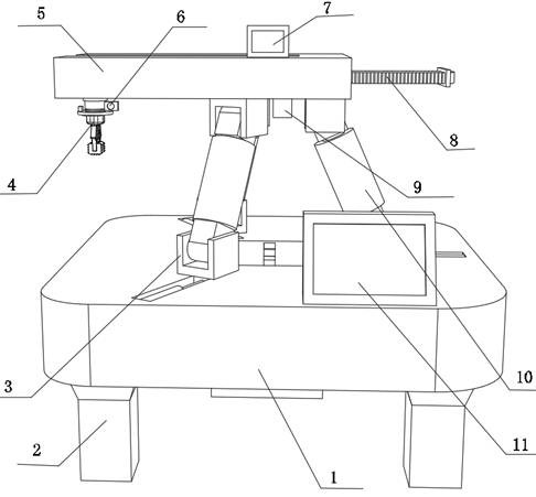
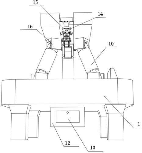
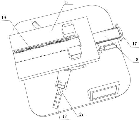
[0042] A high-precision manipulator, such as Figure 1-4 As shown, including the body 1, the bottom outer wall of the body 1 is fixed with four legs 2 by bolts; the top outer wall of the body 1 is provided with three placement grooves 37, and the inner walls of the three placement grooves 37 are all fixed by bolts. Hydraulic cylinder 18, the extension ends of the three hydraulic cylinders 18 are all fixed with the lower connecting seat 3 by bolts, the three lower connecting seats 3 form sliding fit with the three placement grooves 37 respectively, the lower connecting seat 3 is a C-shaped structure, three One side of the inner wall of the lower connecting seat 3 is slidably connected with an electric telescopic assembly 10 through a slider, one side of the outer wall of the three electric telescopic assemblies 10 is connected with an upper connecting seat 16 through a rotating shaft, and the top outer walls of the three upper connecting seats 16 are The same fixed seat 5 is fi...

Embodiment 2

[0049] A method of controlling a manipulator with high precision, such as Figure 1-7 shown, including the following steps:

[0050] S1: Load the objects to be transported into the collection box 12;

[0051] S2: Control and start two first motors 7 that rotate asynchronously, and drive the moving rod 8 to move forward and backward through the gear 19;

[0052] S3: When the infrared receiver 6 receives the light curtain signal from the infrared emitter 9, it controls the first motor 7 to turn off, and then adjusts the lifting structure to drive the manipulator 4 to descend to pick up the object;

[0053] S4: when picking and transferring objects, the infrared light 34 is turned on, and its light is used as a reference point for the manipulator 4 to pick;

[0054] S5: The camera 31 captures the image in real time and transmits it to the display screen 11 for display as a reference;

[0055] S6: After retrieving the material successfully, control and start the first motor 7 t...


PUM


Abstract

The invention discloses a mechanical arm with high precision and a control method thereof, and relates to the technical field of mechanical arms. The mechanical arm aims to solve the problems that a mechanical arm is prone to shaking and being unstable, and quite manpower is consumed. The mechanical arm comprises a machine body, and four supporting legs are arranged on the outer wall of the bottom of the machine body. Three containing grooves are formed in the outer wall of the top of the machine body, hydraulic cylinders are arranged on the inner walls of the three containing grooves, lower connecting bases are arranged at the extending ends of the three hydraulic cylinders, the three lower connecting bases are in sliding fit with the three containing grooves correspondingly, the lower connecting bases are of C-shaped structures, and an electric telescopic assembly is arranged on the inner wall of one side of each of the three lower connecting bases. The control method of the mechanical arm comprises the following steps that objects needing to be conveyed are loaded into a collecting box; and two first motors which do not rotate synchronously are controlled to be started. By means of the mechanical arm, the situation that the stable conveying structure shakes due to the fact that the carrying range is too large can be avoided, manpower is saved, and the adjusting operation efficiency is greatly improved.

Description

technical field [0001] The invention relates to the technical field of manipulators, in particular to a manipulator with high precision and a control method thereof. Background technique [0002] In today's life, with the rapid development of science and technology, the biggest difference between robotic arms and human arms lies in flexibility and endurance. That is, the biggest advantage of the manipulator is that it can do the same action repeatedly. The manipulator is a common mechanism in automation equipment and can be used to grab and carry objects. An important branch of the industrial manipulator robot, the manipulator can be driven by a variety of driving mechanisms, and the manipulator can be divided into hydraulic, pneumatic, electric and mechanical according to the driving mode. The characteristic is that various expected operations can be completed through programming. Most of the existing manipulators can only perform simple functions of grabbing, shifting po...

Claims


Application Information

Patent Timeline
Patent Type & Authority Applications(China)
IPC IPC(8): B25J9/16B25J13/00B25J18/00B25J19/02B25J19/04
CPCB25J18/00B25J9/161B25J9/1612B25J13/00B25J19/021B25J19/04
Inventor 柳斯
Owner 柳斯
Why Eureka
Try Eureka