Composite soluble bridge plug

A bridge plug and vertebral body technology, applied in the field of composite soluble bridge plugs, can solve the problems of unreasonable connection mode, many connecting parts, complex structure and the like

Pending Publication Date: 2021-05-18
DAQING TIANDEZHONG PETROLEUM SCI & TECH CO LTD
View PDF9 Cites 0 Cited by
  • Summary
  • Abstract
  • Description
  • Claims
  • Application Information

AI Technical Summary

Problems solved by technology

[0003] The main body of the anchoring slips is composed of soluble metal and insoluble particles. After dissolution, undissolved residues such as slips and slips remain in the wellbore. In the later stage, coiled tubing strings and fishing tool strings need to be run into the well. , Salvage construction operations, long operating cycle, low salvage efficiency, affecting the construction progress on site, so now there are some soluble bridge plugs, but the structure is more complicated, too many connectors, and the connection method is unreasonable, resulting in processing difficulties and cost too high;
[0004] Notification number CN 110552659 B discloses a metal soluble bridge plug, which includes a setting cylinder, an upper vertebral body, a sealing cylinder, a lower The sealing cylinder, the lower vertebral body and the lower joint are all magnesium-based alloy materials, and the dissolution rate is the same under the same environmental conditions. However, the dissolution rate of the soluble magnesium-based alloy material in a certain solution (mg·cm-2· h-1) is the same, but the volume and thickness of each part are different, and the dissolution time of each part is still different. The pressure of the downhole formation is sealed, but the reverse pressure of the downhole formation cannot be sealed.

Method used


Image

  • Composite soluble bridge plug
  • Composite soluble bridge plug

Examples


Embodiment Construction

[0019] The present invention will be further described below in conjunction with accompanying drawing:

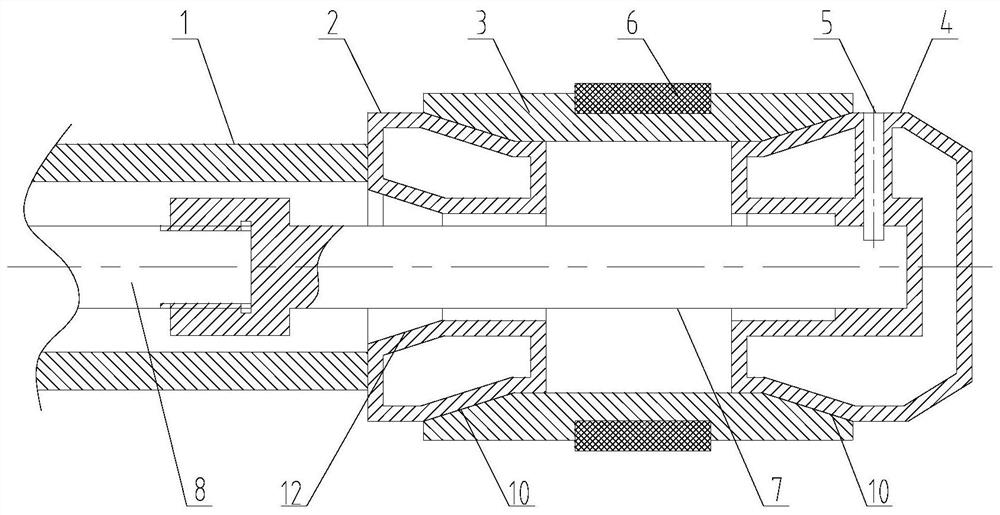
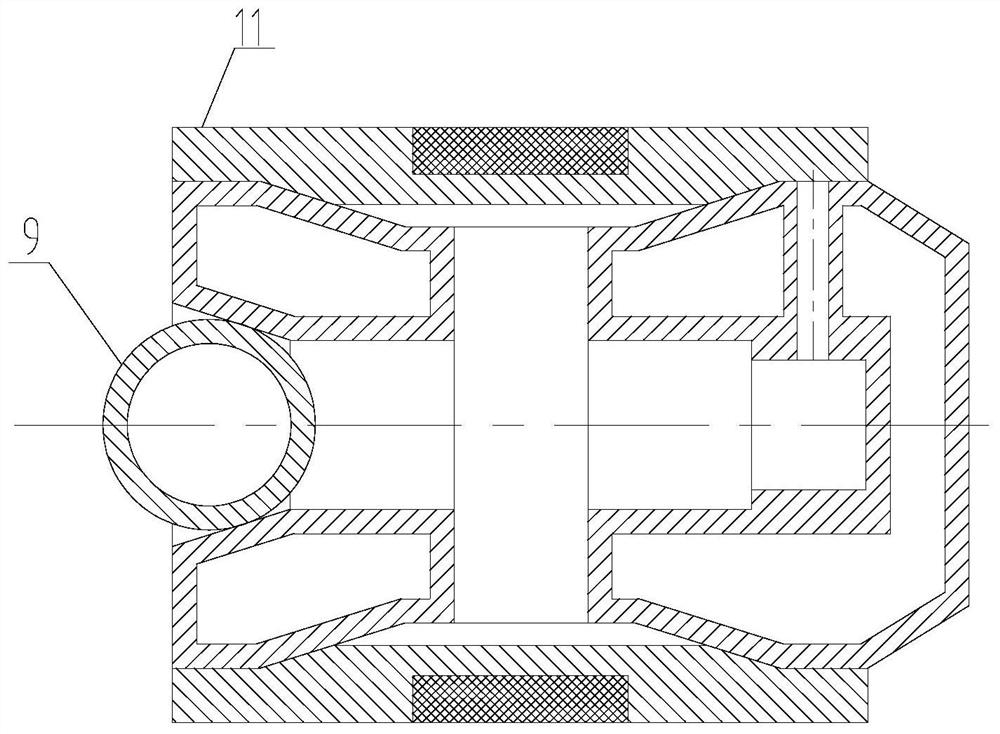
[0020] Depend on figure 1 combine figure 2 As shown, a composite soluble bridge plug includes a setting cylinder 1, an upper vertebral body 2, a sealing cylinder 3, a lower vertebral body 4, a throwing rod 7 and a setting rod 8;

[0021] The lower end of the setting cylinder 1 is attached to the upper surface of the upper vertebral body 2, and the upper end is connected to the peripheral setting tool. In the setting cylinder 1, the lower end of the setting rod 8 is connected to the threaded connection rod 7, and the lower end of the rod 7 is sequentially connected. After passing through the upper vertebral body 2 and the sealing cylinder 3, the throwing rod 7 is connected to the lower vertebral body 4 through the shear pin 5;

[0022] The conical surface of the lower vertebral body 4 cooperates with the lower end of the sealing cylinder 3, and the upper end of the sealin...


PUM


Abstract

The invention provides a composite soluble bridge plug, and relates to the technical field of oil field downhole tools. The lower end of a setting cylinder is attached to the upper end face of an upper cone, the lower end of a setting rod is in threaded connection with a releasing rod, and the releasing rod is connected with a lower cone through a shear pin; and the upper cone, the lower cone and a fracturing ball are all of hollow structures, and the wall thickness of the hollow outer portions is approximately equal to that of a sealing cylinder. The composite soluble bridge plug has the advantages that the upper cone, the sealing cylinder, the lower cone and the fracturing ball are all made of magnesium-based alloy materials, the wall thicknesses of the hollow structures are the same, the dissolution rate and the dissolution time under the same environment condition are the same, and complete dissolution can be achieved in the later period; and an alloy coating is sprayed to the outer portion of the sealing cylinder, the outer surface of the sealing cylinder and the inner wall of a casing pipe are reliably anchored, sealing is achieved through a sealing ring, the fracturing ball seals the upper pressure, the lower cone of a blind plugging structure seals the pressure of the lower stratum, bidirectional sealing is achieved, and meanwhile fine particles are formed after dissolution and discharged along with flowback fluid.

Description

Technical field: [0001] The invention relates to the technical field of oilfield downhole tools, in particular to a composite soluble bridge plug. Background technique: [0002] In the prior art, a soluble bridge plug is mainly composed of a bridge plug body, anchor slips, and a sealing rubber cartridge, among which the bridge plug body is mainly composed of a soluble metal material, which provides an installation carrier for each component and directly determines the safety of the soluble bridge. The overall reliability of the plug; the anchor slip is composed of soluble metal and alloy particles, which prevent the axial sliding of the soluble bridge plug after being anchored to the inner wall of the casing, and directly determine the axial pressure bearing effect of the soluble bridge plug; Composed of soluble rubber material, it will prevent the liquid from flowing down after being bonded to the inner wall of the casing, which directly determines the sealing effect of the...

Claims


Application Information

Patent Timeline
Patent Type & Authority Applications(China)
IPC IPC(8): E21B33/134E21B43/26
CPCE21B33/134E21B43/26
Inventor 张淞源张虎
Owner DAQING TIANDEZHONG PETROLEUM SCI & TECH CO LTD
Why Eureka
Try Eureka