Enthalpy-increasing continuous combustion propelling device

A propulsion device, self-increasing technology, applied in the field of launch, can solve the problems of complex operation, overheating, large current, etc.

Pending Publication Date: 2021-05-18
UNIV OF SCI & TECH OF CHINA
View PDF0 Cites 0 Cited by
  • Summary
  • Abstract
  • Description
  • Claims
  • Application Information

AI Technical Summary

Problems solved by technology

However, the acceleration projectile of the electromagnetic gun needs to be accelerated by multi-stage coils. The operation of the acceleration process is very complicated. It can only launch ultra-high-speed fragments of the gram mass level, and when the capacitor charges and discharges the coil, the current is very large, which will cause overheating and reduce the electromagnetic force. gun life

Method used


Image

  • Enthalpy-increasing continuous combustion propelling device
  • Enthalpy-increasing continuous combustion propelling device
  • Enthalpy-increasing continuous combustion propelling device

Examples


Embodiment 1

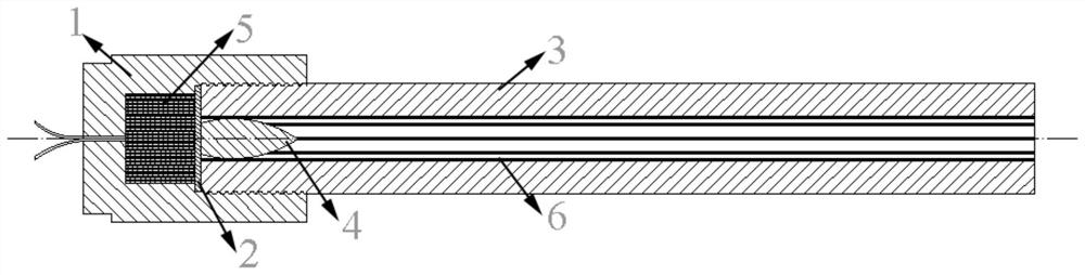
[0027] refer to figure 1 , first select the body tube 3, process a rectangular groove inside the body tube 3, carry out the groove charge 6, and place the projectile 4 at one end of the body tube 3; then carry out the propellant charge in the launching mechanism 1, Place the tablet 2 between the launch mechanism 1 and the barrel 3; then insert a section of the combined barrel with the projectile 4 into the launch mechanism 1 through threads; then fix the installed device; Detonate.

Embodiment 2

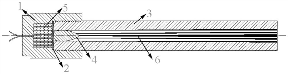
[0029] refer to figure 2 , first select the barrel 3, process it into a groove with gradually increasing size inside the barrel 3, carry out the groove charge 6, and place the projectile 4 at one end of the barrel 3; then carry out the propellant in the launching mechanism 1 Charge the medicine, place the medicine blocking piece 2 between the launch mechanism 1 and the barrel 3; then insert a section of combined barrel with the projectile 4 into the launch mechanism 1 through threads; then fix the installed device; finally pass the launch The detonator detonates.

Embodiment 3

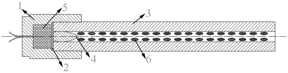
[0031] refer to image 3 , first select the barrel 3, inside the barrel 3 there are pits of a certain size and depth, the pits are arranged in a spiral distribution, carry out the pit charge 6, and place the projectile 4 at one end of the barrel 3; then launch Carry out the propellant charge in the mechanism 1, place the drug blocking sheet 2 between the launching mechanism 1 and the barrel 3; then insert a section of combined barrel with the projectile 4 into the launching mechanism 1 through threads; then place the installed The device is fixed; finally detonated by the detonator.

[0032]In each of the above-mentioned embodiments, the high-temperature and high-pressure gas produced by the propellant in the launching mechanism 1 under the action of the detonator will shear the drug blocking piece 2 along the axial direction of the barrel 3, so that the cut circle The sheet pushes the projectile 4 to move at high speed under the action of high-pressure gas, which ensures a c...


PUM


Abstract

The invention discloses an enthalpy-increasing continuous combustion propelling device which comprises a charging structure regularly arranged on the inner wall of a barrel, and the charging form can be a groove, a powder chamber and the like. After a projectile is propelled by a primer, shock waves are formed forward, and a charging structure is ignited under the compression of high-temperature and high-pressure fuel gas, solid particles and the shock waves at the bottom of the projectile; the pressure gradient formed in the rear space of the projectile due to high-speed movement of the projectile is reduced, the influence of sparse waves is weakened, and high and approximately constant pressure is formed at the bottom of the projectile; and the enthalpy value of a system behind the projectile is increased, and the total temperature is increased, so that the projectile reaches a higher speed. According to the structure charging, gaps between riflings in the gun barrel , or grooves, pits and the like can be adopted for charging, and the arrangement form, such as spiral distribution and linear distribution, is determined according to the requirements. According to the propelling device, not only is the outlet speed of the projectile increased, but also the chamber pressure of a main powder chamber is further reduced.

Description

technical field [0001] The invention belongs to the technical field of launching, and in particular relates to a self-increasing enthalpy continuous dynamic combustion propulsion device. Background technique [0002] Due to the indisputable superiority of high muzzle velocity projectile launching devices in modern technology, researchers from all over the world have been exploring and studying how to increase the launch velocity of projectiles or fragments. From the early artillery and light gas guns to the later electromagnetic guns and electrothermal chemical guns, a series of new acceleration methods have been developed. Although the above methods have their own advantages at present, due to the influence of the current basic conditions, funds and applications, it is still difficult to apply their technology to actual combat and engineering damage end-point effect impact experiments in a short period of time. [0003] Current launching devices are mainly based on artille...

Claims


Application Information

Patent Timeline
IPC IPC(8): F41F1/00
CPCF41F1/00
Inventor 马宏昊陈子俊王鲁庆赵凯孙玉玲沈兆武
Owner UNIV OF SCI & TECH OF CHINA
Why Eureka
Try Eureka