
Active vision SLAM system based on panoramic camera

A panoramic camera and active vision technology, which is applied to the components of TV systems, radio wave measurement systems, TVs, etc., can solve the problems of small visual field, inability to guarantee image collection, and small amount of image information

Active Publication Date: 2021-05-18
BEIHANG UNIV
View PDF9 Cites 6 Cited by
  • Summary
  • Abstract
  • Description
  • Claims
  • Application Information

AI Technical Summary

Problems solved by technology

First of all, the current visual SLAM has the disadvantages of small field of view of the sensor and small amount of collected image information.
For example, in the SLAM navigation-based photovoltaic power plant operation and maintenance robot charging system disclosed in Chinese patent CN111176300A, the light field camera installed on the operation and maintenance robot has a relatively small visual field of view and a small amount of image information collected at the same time.
Secondly, the current visual SLAM has the disadvantages of being easily affected by changes in illumination and not performing well in places where the environment texture is not rich.
For example, in the green pruning robot based on visual SLAM disclosed in Chinese patent CN211580758U, since the device does not have a good coping strategy in the face of outdoor environmental light changes and scenes with poor environmental textures, the visual SLAM system may not be able to effectively establish Environment map and self-orientation
Finally, visual SLAM also has the disadvantages that the visual exploration process is too blind, and the efficiency of mapping and positioning is not high.
Such as Chinese patent CN104062977B disclosed in the fully autonomous flight control method of quadrotor UAV based on visual SLAM, the device uses the camera installed at the bottom of the quadrotor UAV to collect image information. Insufficient restrictions, without interfering with the original trajectory of the drone, it is impossible to guarantee that the most suitable image for the visual SLAM system can be collected

Method used


Image

  • Active vision SLAM system based on panoramic camera
  • Active vision SLAM system based on panoramic camera
  • Active vision SLAM system based on panoramic camera

Examples


Embodiment Construction

[0042] The present invention will be further described below in conjunction with the accompanying drawings and examples. It should be understood that the following examples are intended to facilitate the understanding of the present invention, and have no limiting effect on it.

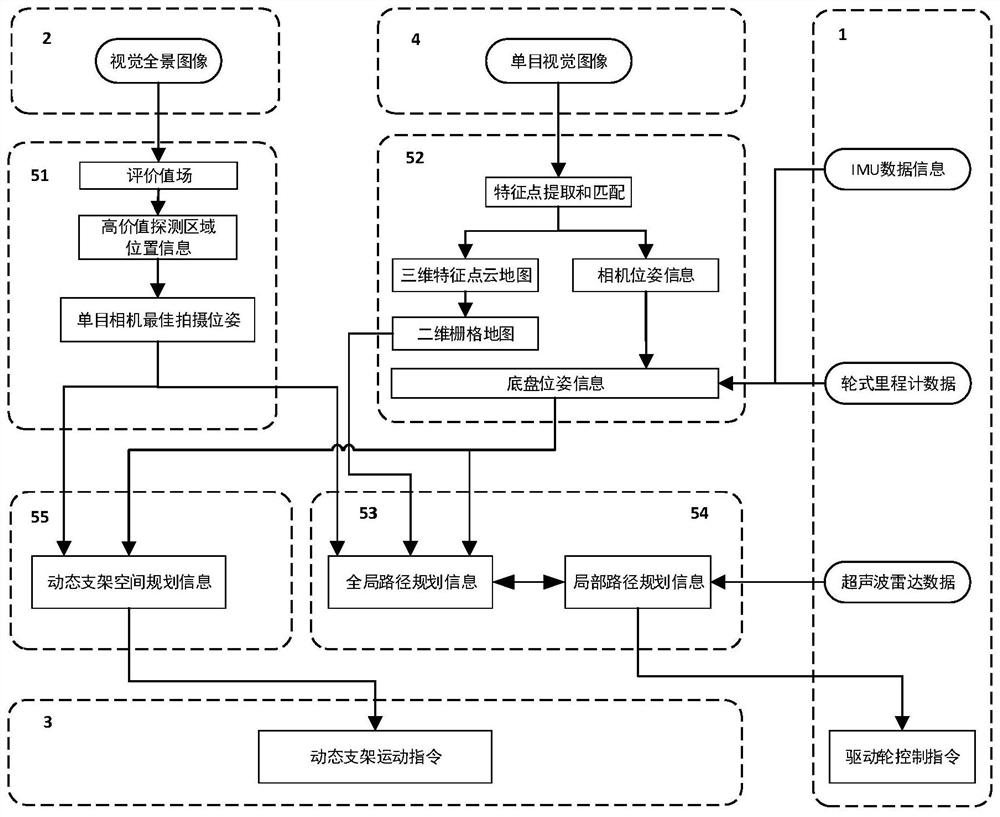
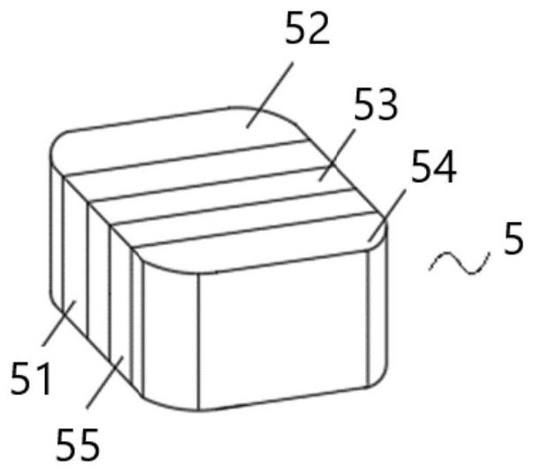
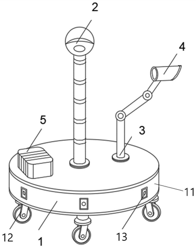
[0043] Such as figure 1 As shown, the panoramic camera-based active vision SLAM system provided in this embodiment includes an intelligent navigation chassis module 1 , a panoramic camera module 2 , a camera dynamic bracket 3 , a monocular camera module 4 and a processor 5 . Wherein, the processor 5 includes an evaluation module 51, a visual SLAM processing module 52, a global planning module 53, a local path planning module 54 and a dynamic support planning control module 55, such as figure 2 shown.

[0044] In this embodiment, the intelligent chassis module 1 includes a chassis 11, three moving wheels 12, a driving wheel control module, six ultrasonic radars 13, an IMU sensor and a wheel odometer....


PUM


Abstract

The invention belongs to the technical field of visual SLAM processing technology and mobile chassis navigation path planning, and particularly relates to an active visual SLAM system based on a panorama camera, which comprises an intelligent chassis module, a panorama camera module, a camera dynamic bracket, a monocular camera module and a processor; the processor comprises an evaluation module, a visual SLAM processing module, a global planning module, a local path planning module and a dynamic support planning control module. By adding the intelligent chassis module capable of doing curvilinear motion at any radius, the monocular camera module installed on the multi-degree-of-freedom camera dynamic support and the panoramic camera module used for evaluating the whole environment, the problem that traditional visual SLAM mapping scanning is not purposeful is solved. According to the invention, visual mapping and positioning are more purposeful, the mapping and positioning speed is increased, the mapping and positioning quality is improved, and the mapping and positioning reliability and flexibility are enhanced.

Description

technical field [0001] The invention belongs to the field of visual simultaneous localization and mapping (SLAM) processing technology and mobile chassis navigation path planning technology, and in particular relates to an active visual SLAM system based on a panoramic camera. Background technique [0002] In recent years, SLAM processing technology has developed rapidly. It obtains information about the surrounding environment through visual sensors such as monocular cameras, binocular cameras, or depth cameras, or laser sensors such as lidar, and can solve the position and motion of the sensor itself through specific calculation methods. trajectory, and at the same time build a three-dimensional map of the surrounding environment. Visual SLAM technology has always been a key research technology in the fields of robot autonomous navigation, assisted driving, augmented reality and 3D reconstruction. It is closely related to technologies such as visual image processing, featu...

Claims


Application Information

Patent Timeline
IPC IPC(8): G06T17/00G06T3/00G06T3/40H04N5/232G01S15/931F16M11/12F16M11/42
CPCG06T17/00G06T3/4038G01S15/931F16M11/42F16M11/12H04N23/695G06T3/14
Inventor 徐国艳陈冠宏周彬陈志发廖亚萍
Owner BEIHANG UNIV
Learn More