Pulse detection circuit and pulse detection method

A pulse detection and circuit technology, applied in the electronic field, can solve the problems of high power consumption, increased cost, and reduced performance of microcontrollers, etc., to achieve reduced power consumption, increased flexibility, composability and reusability Effect

Pending Publication Date: 2021-05-21
GREE ELECTRIC APPLIANCES INC
View PDF0 Cites 0 Cited by
  • Summary
  • Abstract
  • Description
  • Claims
  • Application Information

AI Technical Summary

Problems solved by technology

[0003] With the rise of the Internet of Things industry and wearable devices, low power consumption has become a very important research direction, but the traditional high-speed pulse measurement method needs a high-speed clock for counting. If you want to realize the automatic detection of high-speed pulses, you need to synchronize The participation of the device will generate a large power consumption
At present, there are many ways to reduce the power consumption of the microcontroller. Usually, the overall power consumption of the chip is reduced by reducing the main frequency or improving the process, but reducing the main frequency will reduce the performance of the microcontroller, and the advanced process will increase cost

Method used


Image

  • Pulse detection circuit and pulse detection method
  • Pulse detection circuit and pulse detection method
  • Pulse detection circuit and pulse detection method

Examples


Embodiment Construction

[0034] In order to make the purpose, technical solutions and advantages of the application clearer, the technical solutions in the embodiments of the application will be clearly and completely described below in conjunction with the drawings in the embodiments of the application. Obviously, the described embodiments are only It is a part of the embodiments of this application, not all of them. Based on the embodiments in this application, all other embodiments obtained by persons of ordinary skill in the art without making creative efforts belong to the scope of protection of this application. In the case of no conflict, the embodiments in the present application and the features in the embodiments can be combined arbitrarily with each other. Also, although a logical order is shown in the flowcharts, in some cases the steps shown or described may be performed in an order different from that herein.

[0035] The terms "first" and "second" in the specification and claims of the...


PUM


Abstract

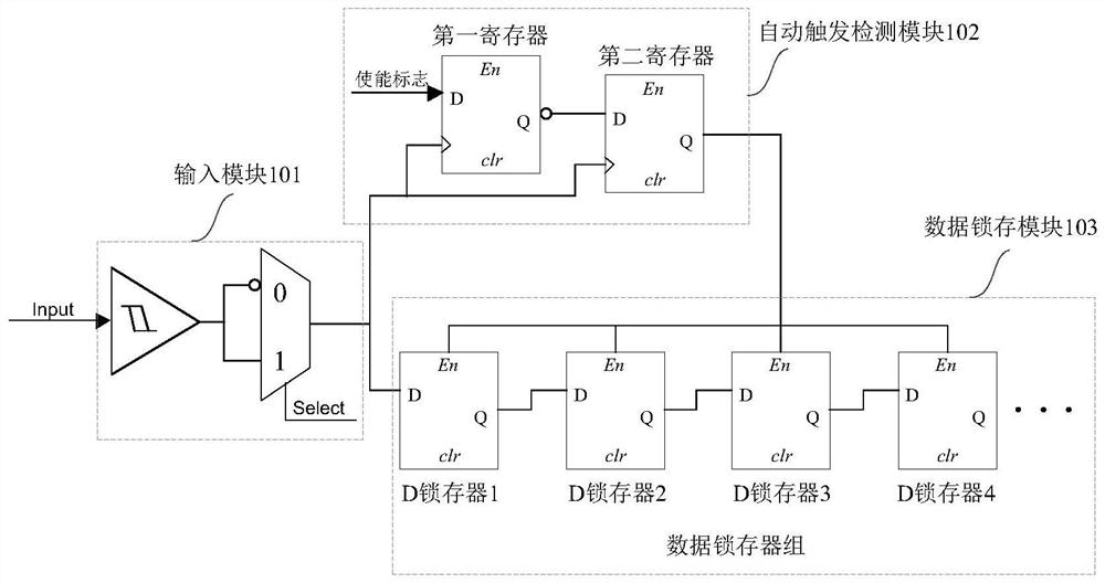
The invention discloses a pulse detection circuit and a pulse detection method, which can measure a higher-speed input pulse while reducing the power consumption of a microcontroller. The pulse detection circuit comprises an input module, an automatic trigger detection module and a data latching module. The input end of the input module receives an external input pulse, a pulse signal is transmitted to the clock pulse end of the automatic trigger detection module and the input end of the data latching module through the output end of the input module, and when the pulse signal is changed from a first level to a second level, the automatic trigger detection module is enabled, and the output end of the automatic trigger detection module sends a latch signal to the enabling end of the data latching module, so that the data latching module latches the pulse signal according to the latch signal.

Description

technical field [0001] The present application relates to the field of electronic technology, in particular to a pulse detection circuit and a pulse detection method. Background technique [0002] At present, with the continuous improvement of the frequency of pulse signals, high-speed pulses are widely used in the field of electronic research, and the progress of high-speed pulse technology is inseparable from the development of pulse measurement technology. Therefore, research on new technologies for measuring high-speed pulses and understanding pulse Width, phase and shape information are very important research contents. [0003] With the rise of the Internet of Things industry and wearable devices, low power consumption has become a very important research direction, but the traditional high-speed pulse measurement method needs a high-speed clock for counting. If you want to realize the automatic detection of high-speed pulses, you need to synchronize The participation...

Claims


Application Information

Patent Timeline
Patent Type & Authority Applications(China)
IPC IPC(8): G01R29/02G01R29/04G01R25/00G01R1/30
CPCG01R1/30G01R25/00G01R29/023G01R29/04
Inventor 翟正涛
Owner GREE ELECTRIC APPLIANCES INC
Why Eureka
Try Eureka