
New energy automobile part assembling facility

A new energy vehicle and component assembly technology, applied in the field of auto parts, can solve the problems of inability to meet market demand, low degree of automation, and more manual intervention, and achieve the effect of high degree of automation, less manual intervention, and increased production speed

Inactive Publication Date: 2021-05-28
李为
View PDF0 Cites 2 Cited by
  • Summary
  • Abstract
  • Description
  • Claims
  • Application Information

AI Technical Summary

Problems solved by technology

[0005] In order to overcome the above-mentioned defects of the prior art, an embodiment of the present invention provides a new energy automobile parts assembly equipment. The technical problem to be solved by the present invention is: the existing automobile parts have a low degree of automation when the shaft hole interference fit , more manual intervention, slow production speed, unable to meet market demand

Method used


Image

  • New energy automobile part assembling facility
  • New energy automobile part assembling facility
  • New energy automobile part assembling facility

Examples


Embodiment Construction

[0035] Example embodiments will now be described more fully with reference to the accompanying drawings. Example embodiments may, however, be embodied in many forms and should not be construed as limited to the examples set forth herein; Fully conveyed to those skilled in the art. The drawings are merely schematic illustrations of the present disclosure and are not necessarily drawn to scale. The same reference numerals in the drawings denote the same or similar parts, and thus repeated descriptions thereof will be omitted.

[0036] Furthermore, the described features, structures, or characteristics may be combined in any suitable manner in one or more example embodiments. In the following description, numerous specific details are provided in order to give a thorough understanding of example embodiments of the present disclosure. However, those skilled in the art will appreciate that the technical solutions of the present disclosure may be practiced without one or more of ...


PUM


Abstract

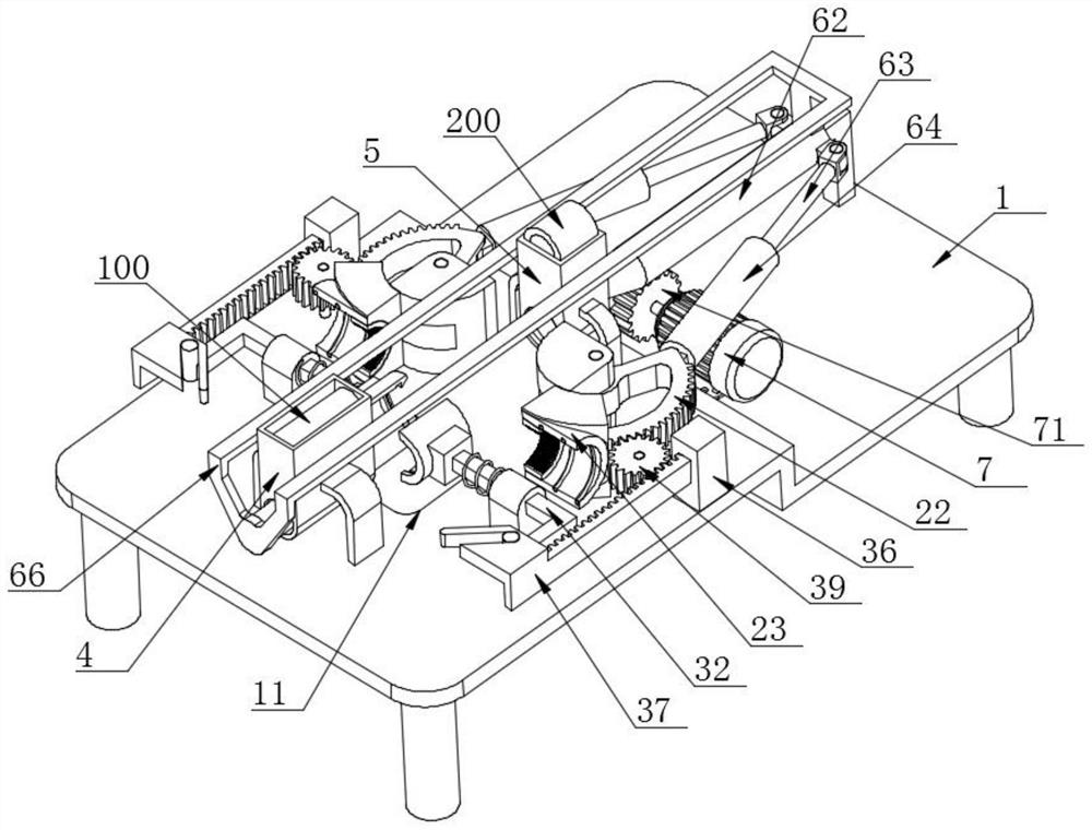
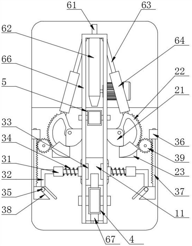
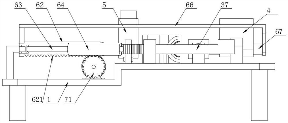
The invention discloses a new energy automobile part assembling facility, and particularly relates to the technical field of automobile parts. The facility comprises a machine frame, wherein a discharging opening is formed in one side of the middle of the machine frame, cleaning and heating mechanisms are arranged on the two sides of the middle of the top of the machine frame, clamping mechanisms are arranged on the same sides of the two cleaning and heating mechanisms, and a first material barrel is arranged on the sides, far away from the cleaning and heating mechanisms, of the two clamping mechanisms. According to the facility, two semi-cylindrical cleaning brushes and two semi-high-frequency induction heating coils can be combined through rotation of two arc-shaped racks towards the middle, so that the purposes of cleaning the surface of a hole piece and increasing the hole diameter through high-frequency induction heating are achieved; the purpose of clamping and positioning the hole piece is achieved through the combination of two semi-cylindrical clamping blocks, and the purpose that a rear push column pushes a shaft piece to enter an inner hole of the hole piece to achieve assembly is achieved; and the two semi-cylindrical clamping blocks can be automatically separated, and therefore the purpose of automatic discharging is achieved.

Description

technical field [0001] The invention relates to the technical field of auto parts, and more specifically, the invention relates to a new energy auto parts assembly equipment. Background technique [0002] With the rapid rise of new energy vehicles, great changes have taken place in the ecology of the automotive industry, and automotive products are developing in the direction of low-carbon, electric, and intelligent. At present, there are two sources of power for new energy vehicles, one is gasoline-electric hybrid The electric hybrid type uses the fuel engine as the main power and the electric motor as the auxiliary power. The other is the pure electric type. Optimizing the vehicle structure and reducing production costs, new energy vehicles can greatly reduce environmental pollution, meet the requirements of low-carbon environmental protection, become the future development trend, and will eventually replace traditional fuel vehicles When mating, it is usually possible to...

Claims


Application Information

Patent Timeline
Patent Type & Authority Applications(China)
IPC IPC(8): B23P19/12B23P11/02B08B9/027
CPCB08B9/027B23P11/025B23P19/12
Inventor 李为
Owner 李为
Learn More