Supercharge Your Innovation With Domain-Expert AI Agents!

Humidifying and dedusting environmental protection equipment

A technology of environmental protection equipment and dust removal components, applied in lighting and heating equipment, air humidification systems, heating methods, etc., can solve the problems of inability to remove dust and other impurities, adverse to people's health, low work efficiency, etc., to protect physical health, The effect of increasing the humidification range and improving work efficiency

Inactive Publication Date: 2021-05-28
王天颖
View PDF5 Cites 0 Cited by
  • Summary
  • Abstract
  • Description
  • Claims
  • Application Information

AI Technical Summary

Problems solved by technology

[0004] The purpose of the present invention is to provide an environmental protection equipment for humidification and dust removal, which aims to solve the problem of low working efficiency of the existing environmental protection equipment for humidification and dust removal, which cannot effectively remove and humidify impurities such as dust, which is not conducive to people's health. question

Method used


Image

  • Humidifying and dedusting environmental protection equipment
  • Humidifying and dedusting environmental protection equipment
  • Humidifying and dedusting environmental protection equipment

Examples


Embodiment 1

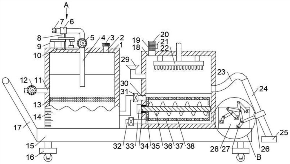
[0023] see Figure 1-4 , in an embodiment of the present invention, an environmental protection device for humidification and dust removal, including a water tank 1, the water tank 1 is connected with a water inlet 2, a first water outlet pipe 4 and a second water outlet pipe 11, and the middle of the first water outlet pipe 4 A first water pump 5 is connected, one end of the first water outlet pipe 4 passes through the water tank 1 and extends below the water surface, the other end of the first water outlet pipe 4 is connected with a first nozzle 7, and the water tank 1 is connected with a base 15, The first water outlet pipe 4 is clamped with a first clamping rod 6 , the first clamping rod 6 is connected with a sliding assembly connected with the water tank 1 , and the second water outlet pipe 11 is connected with a dust removal assembly.

[0024] In the embodiment of the present invention, the first water pump 5 is turned on, and the first water pump 5 extracts the water in...

Embodiment 2

[0026] see figure 1 , as a preferred embodiment of the present invention, the material of the water tank 1 is a transparent material, the surface of the water tank 1 is connected with a scale mark 14, the water inlet 2 is threadedly connected with a tank cover 3, and the four corners of the bottom surface of the base 15 are fixed Universal wheels 16 are connected, and armrests 17 are fixedly connected to the side of the base 15 .

[0027] In an embodiment of the present invention, the water tank 1 is set to be made of a transparent material and a scale mark 14, which is convenient for people to observe the amount of water in the water tank 1. A red warning water level is provided in the scale mark 14, which is convenient for reminding people to add water to the water tank 1. The tank cover 3 acts as a seal to prevent impurities such as dust in the air from entering the water tank 1. The outer surface of the tank cover 3 is treated with anti-slip treatment to facilitate tighten...

Embodiment 3

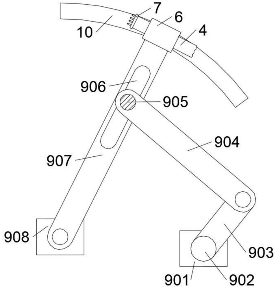
[0029] see Figure 1-2, as a preferred embodiment of the present invention, the sliding assembly includes a sliding block 8 fixedly connected with the first clamping rod 6, and the sliding block 8 is fixedly connected with a reciprocating assembly 9 fixedly connected with the water tank 1, so The water tank 1 is provided with a chute 10 that is slidably connected with the slider 8 .

[0030] In the embodiment of the present invention, the reciprocating component 9 drives the slider 8 to slide with the chute 10 in the water tank 1 , drives the first clamping rod 6 to move, and then drives the first spray head 7 to rotate.


PUM


Abstract

The invention relates to the technical field of environment protection equipment, in particular to humidifying and dedusting environment protection equipment. The equipment comprises a water tank, wherein the water tank is connected with a water inlet, a first water outlet pipe and a second water outlet pipe, a first water pump is connected to the middle of the first water outlet pipe, one end of the first water outlet pipe penetrates through the water tank and extends to the position below the water surface, the other end of the first water outlet pipe is connected with a first spray head, the water tank is connected with a base, the first water outlet pipe is connected with a first clamping rod in a clamped mode, the first clamping rod is connected with a sliding assembly connected with the water tank, and the second water outlet pipe is connected with a dust removal assembly. The device solves the problems that existing environment protection humidifying and dedusting equipment is low in working efficiency, cannot effectively remove and humidify impurities such as dust and is not beneficial to body health of people, is reasonable in structural design, improves the working efficiency of the equipment, can effectively remove the impurities such as the dust and increase the air humidity, a comfortable living environment is provided, and the body health of people is protected.

Description

technical field [0001] The invention relates to the technical field of environmental protection equipment, in particular to environmental protection equipment for humidification and dust removal. Background technique [0002] Environmental protection equipment refers to mechanical products, structures and systems manufactured and constructed by production units or construction installation units for controlling environmental pollution and improving environmental quality. Environmental protection equipment not only refers to mechanically processed products that control environmental pollution, such as dust collectors, welding fume purifiers, monomer water treatment equipment, noise controllers, etc.; it also includes power equipment that transports fluid substances containing pollutants, such as water pumps, fans, Conveyors, etc.; it also includes monitoring and control instruments to ensure the normal operation of pollution prevention and control facilities, such as testing ...

Claims


Application Information

Patent Timeline
Patent Type & Authority Applications(China)
IPC IPC(8): F24F6/14F24F8/133F24F8/142B01D47/06C02F1/52
CPCF24F6/14B01D47/06C02F1/5281F24F2006/146
Inventor 王天颖
Owner 王天颖
Features
  • R&D
  • Intellectual Property
  • Life Sciences
  • Materials
  • Tech Scout
  • Unparalleled Data Quality
  • Higher Quality Content
  • 60% Fewer Hallucinations
Learn More