
Super-resolution microscopic imaging system

A microscopic imaging and super-resolution technology, which is applied in the direction of material analysis, material excitation analysis, and material analysis through optical means, to achieve the effects of improving precision and accuracy, reducing costs, and real-time axial drift correction

Pending Publication Date: 2021-05-28
山东迈科显微生物科技有限公司
View PDF0 Cites 2 Cited by
  • Summary
  • Abstract
  • Description
  • Claims
  • Application Information

AI Technical Summary

Problems solved by technology

[0004] An embodiment of the present invention provides a super-resolution microscopic imaging system to improve the compactness and controllability of the system, thereby solving the problem of collecting original image information of in-situ real-time molecular activities in cells, and improving the existing single-molecule localization. Precision and accuracy of microscopic methods

Method used


Image

  • Super-resolution microscopic imaging system
  • Super-resolution microscopic imaging system

Examples


Embodiment 1

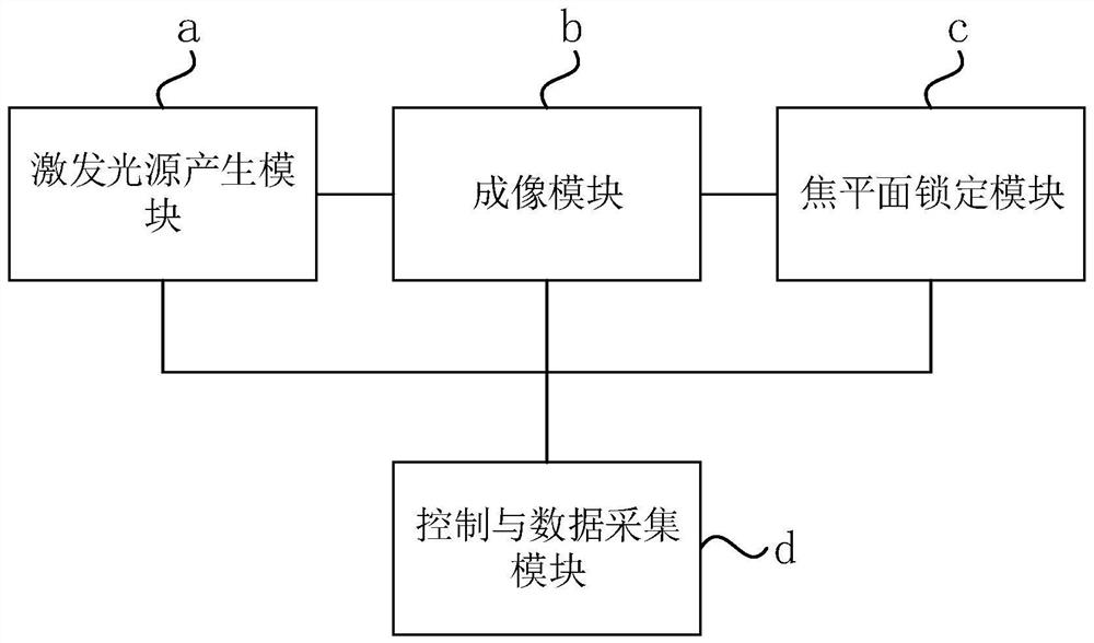
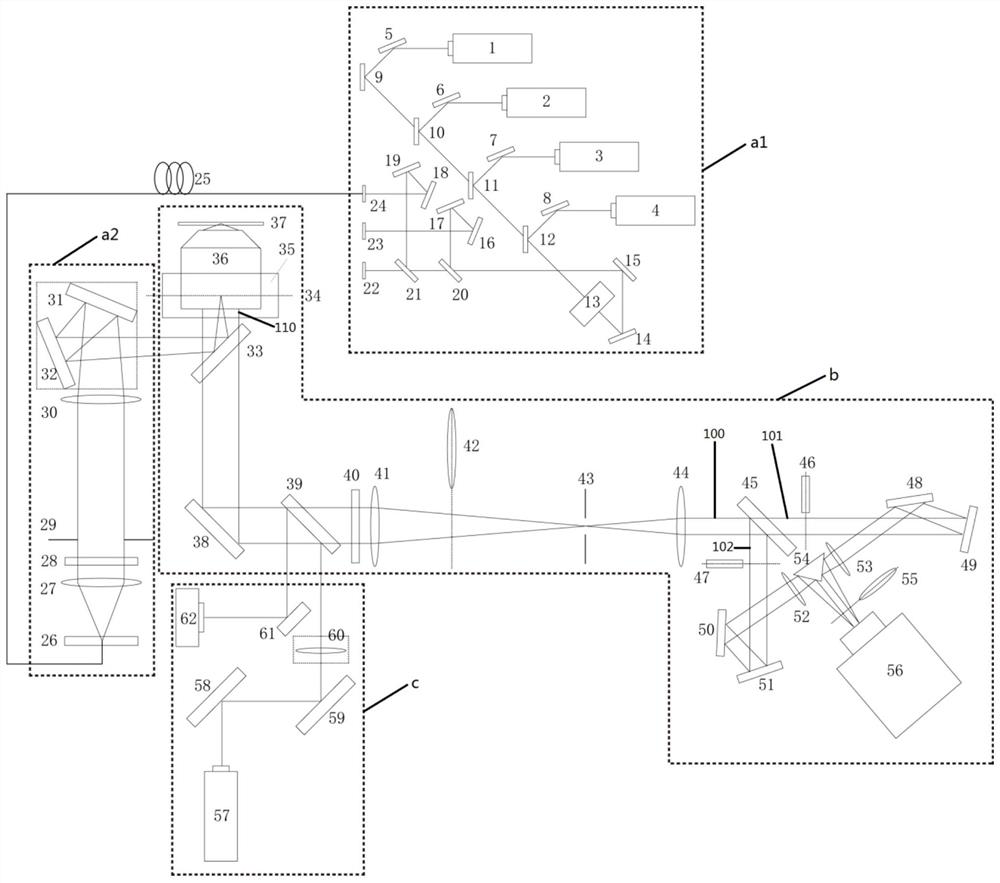
[0025] figure 1 It is a schematic structural diagram of a super-resolution microscopic imaging system provided in Embodiment 1 of the present invention. Such as figure 1 As shown, the system includes: excitation light source generation module a, imaging module b, focal plane locking module c, and control and data acquisition module d; wherein, excitation light source generation module a is used to generate excitation light source; imaging module b is used to receive excitation The light source is to irradiate the excitation light source on the sample of the sample slide to generate fluorescence in the field of view of the sample, and collect the reflected fluorescence through the camera; the focal plane locking module c is used to emit laser light to the imaging module b, and receive the reflection reflected by the imaging module b The returned laser is used to measure and lock the distance between the objective lens and the sample slide in the imaging module b; the imaging m...


PUM

PropertyMeasurementUnit
sizeaaaaaaaaaa
wavelengthaaaaaaaaaa

Abstract

The embodiment of the invention discloses a super-resolution microscopic imaging system. The system comprises an excitation light source generation module, an imaging module, a focal plane locking module and a control and data acquisition module, wherein the excitation light source generation module is used for generating an excitation light source; the imaging module is used for receiving the excitation light source, enabling the excitation light source to irradiate a sample on the sample slide to enable a view field area of the sample to generate fluorescent light, and collecting the reflected fluorescent light through the camera; the focal plane locking module is used for emitting laser to the imaging module and receiving the laser reflected by the imaging module so as to lock the distance between an objective lens in the imaging module and a sample slide; and the control and data acquisition module is used for controlling and adjusting optical elements in the excitation light source generation module, the imaging module and the focal plane locking module, and acquiring fluorescence data obtained by the imaging module for data analysis. According to the system, a compact, adjustable and controllable single-molecule positioning microtechnique with high automation degree is realized, and the precision and the accuracy are improved.

Description

technical field [0001] Embodiments of the present invention relate to the technical field of microscopic imaging, and in particular to a super-resolution microscopic imaging system. Background technique [0002] Fluorescence microscopy has become the most widely used technique for observing and analyzing biological cells due to its good molecular specificity and non-invasive imaging capabilities. Due to the diffraction of light, the resolution of traditional optical microscopes has never been able to break through the Abbe diffraction limit, which is half of the wavelength of light, about 250 nanometers. The size of most biomolecules and molecular complex structures is less than 100 nanometers, so for a long time in the past, researchers were unable to clearly observe the details of biomolecules and cells. In recent years, despite improvements in hardware and imaging methods in X-ray crystallography, nuclear magnetic resonance, and cryo-electron microscopy, it has become po...

Claims


Application Information

Patent Timeline
Patent Type & Authority Applications(China)
IPC IPC(8): G01N21/64G01N21/01
CPCG01N21/01G01N21/6458G01N21/6486
Inventor 李依明何英传
Owner 山东迈科显微生物科技有限公司
Learn More