New energy automobile battery pack heat dissipation device

A technology for new energy vehicles and cooling devices, which is applied to battery pack components, secondary batteries, circuits, etc., and can solve problems such as damaging the battery, affecting the service life of the battery, cooling efficiency, and poor effect

Pending Publication Date: 2021-05-28
付文腾
View PDF0 Cites 8 Cited by
  • Summary
  • Abstract
  • Description
  • Claims
  • Application Information

AI Technical Summary

Problems solved by technology

[0004] The purpose of the present invention is to solve the problem that in the prior art, the battery body is only cooled by natural cooling, the cooling efficiency and effect are poor, and the impact of vibration on the damaged battery shell and internal components when the car bumps during driving The service life of the battery is a problem, and a new energy vehicle battery pack cooling device is proposed

Method used


Image

  • New energy automobile battery pack heat dissipation device
  • New energy automobile battery pack heat dissipation device
  • New energy automobile battery pack heat dissipation device

Examples


Embodiment 1

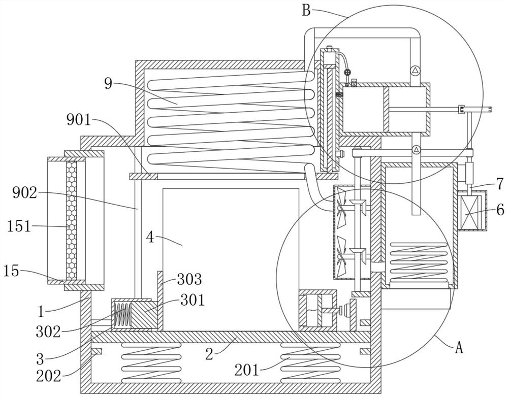
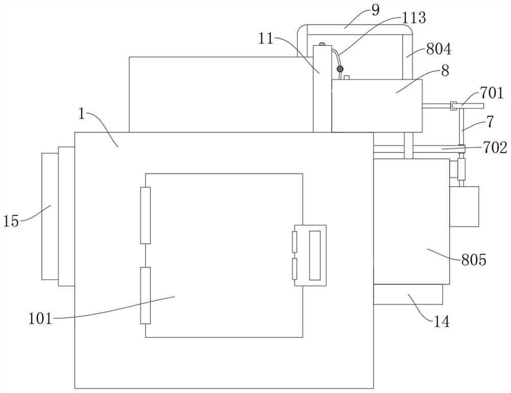
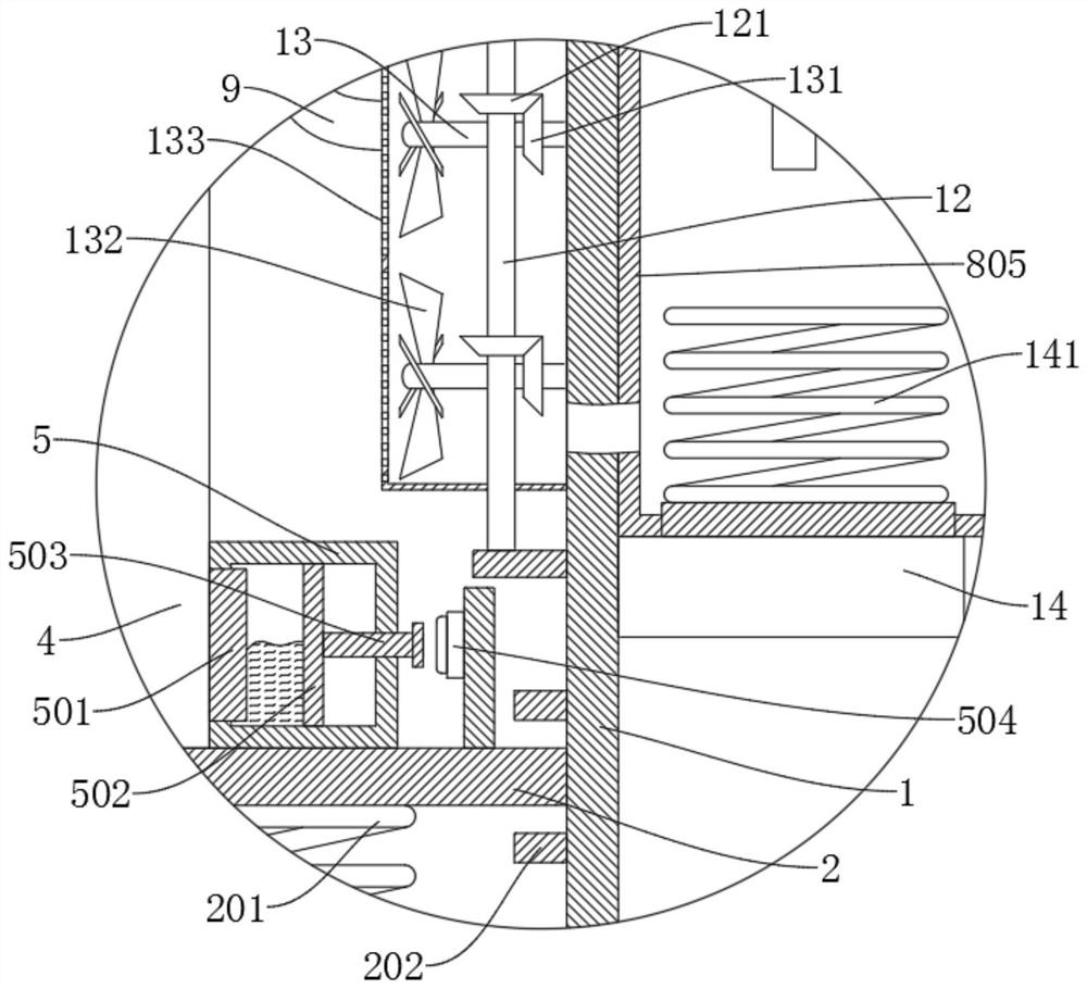
[0038] refer to Figure 1-6 , a heat dissipation device for a new energy vehicle battery pack, comprising a box body 1, a shock absorbing plate 2 is slidably connected to the box body 1, and a first spring 201 is fixedly connected to the bottom of the shock absorbing plate 2, and the first spring 201 is far away from the shock absorbing plate 2 One end is fixedly connected to the inner wall of the box body 1, and the shock absorbing plate 2 is respectively provided with a battery device 4, a clamping mechanism for fixing the battery device 4, and a heat dissipation control mechanism, and the side wall of the box body 1 is provided with a water tank 805, and the water tank 805 The side wall is provided with a driving motor 6, the output end of the driving motor 6 is fixedly connected with the first rotating shaft 7, the first rotating shaft 7 is provided with a cam 701, the side wall of the box body 1 is provided with a cylinder 8, and a piston 801 is slidingly connected in the ...

Embodiment 2

[0041] refer to Figure 1-6 , a heat sink for a battery pack of a new energy vehicle, which is basically the same as that of Embodiment 1, furthermore, the clamping mechanism includes a clamping groove 3, and a clamping rod 301 is slidably connected to the clamping groove 3, and the clamping rod 301 is located at One end in the clamping groove 3 is fixedly connected with a second spring 302, and one end of the second spring 302 away from the clamping rod 301 is fixedly connected to the inner wall of the clamping groove 3, and one end of the clamping rod 301 away from the second spring 302 is fixedly connected with The arrangement of the clamping plate 303 , the clamping groove 3 , the clamping rod 301 , the second spring 302 and the clamping plate 303 is convenient for clamping and fixing the battery device 4 .

Embodiment 3

[0043] refer to Figure 1-6 , a heat dissipation device for a battery pack of a new energy vehicle, which is basically the same as that of Embodiment 1. Further, the heat dissipation control mechanism includes a control tube 5 and a control switch 504, and a heat conduction block 501 is provided on the side wall of the control tube 5, and the heat conduction block 501 and the The battery equipment 4 is attached to each other, a slide plate 502 is slidably connected in the control tube 5, and a pressure bar 503 is fixedly connected to the slide plate 502. The pressure bar 503 matches the control switch 504, and an expansion body is arranged between the heat conducting block 501 and the slide plate 502. After the temperature rises in the working process of the equipment 4, the temperature is transferred to the control tube 5 by the heat conduction block 501, so that the expansion body is heated and expanded to push the sliding plate 502 to slide, and then the pressure rod 503 pre...


PUM


Abstract

The invention discloses a new energy automobile battery pack heat dissipation device, and belongs to the field of new energy automobiles. The new energy automobile battery pack heat dissipation device comprises a box body, a damping plate is slidably connected in the box body, a first spring is fixedly connected to the bottom of the damping plate, and the end, away from the damping plate, of the first spring is fixedly connected to the inner wall of the box body; battery equipment, a clamping mechanism for fixing the battery equipment and a heat dissipation control mechanism are arranged on the damping plate, a water tank is arranged on the side wall of the box body, a driving motor is arranged on the side wall of the water tank, and the output end of the driving motor is fixedly connected with a first rotating shaft; and according to the present invention, the arrangement of the damping plate and the first spring facilitates the vibration damping protection of the battery equipment, the arrangement of the clamping mechanism facilitates the clamping and fixing of the battery equipment, the arrangement of the heat dissipation control mechanism facilitates the control of the operation of the device according to the temperature of the battery equipment, and the arrangement of the spiral pipe, the air cylinder and the water tank facilitates the heat dissipation and cooling of the battery equipment.

Description

technical field [0001] The invention relates to the technical field of new energy vehicles, in particular to a heat dissipation device for a battery pack of a new energy vehicle. Background technique [0002] New energy vehicle batteries can be divided into two categories, namely batteries and fuel cells. Batteries are suitable for pure new energy vehicles and can be classified into lead-acid batteries, nickel-based batteries, sodium beta batteries, secondary lithium batteries, air batteries, etc. , and fuel cells are dedicated to fuel cell new energy vehicles, which can be divided into alkaline fuel cells, phosphoric acid fuel cells, molten carbonate fuel cells, solid oxide fuel cells, proton exchange membrane fuel cells, direct methanol fuel cells, etc. In new energy vehicles, the power battery pack is used as a power source or one of the power sources. Various electrochemical changes and physical changes will occur during the charging and discharging process of the power ...

Claims


Application Information

Patent Timeline
Patent Type & Authority Applications(China)
IPC IPC(8): H01M10/613H01M10/625H01M10/6568H01M10/6563H01M50/242H01M50/249
CPCH01M10/613H01M10/625H01M10/6563H01M10/6568Y02E60/10
Inventor 不公告发明人
Owner 付文腾
Why Eureka
Try Eureka