Semiconductor laser module and optical system

A semiconductor and laser technology, applied in the field of semiconductor laser modules and optical systems, can solve the problems of unfavorable optical element arrangement design, large optical system size, discontinuous light beam, etc. , compact structure

Pending Publication Date: 2021-05-28
FOCUSLIGHT TECH
View PDF9 Cites 0 Cited by
  • Summary
  • Abstract
  • Description
  • Claims
  • Application Information

AI Technical Summary

Problems solved by technology

[0003] For self-space beam combining, although the discontinuity of the outgoing beam is improved, the optical path difference will be formed between the directly outgoing beam and the beam after the reentrant optical path, and the optical path difference will cause the spot formed by the beam combining to be inconsistent. uniform
[0004] In order to eliminate the optical path difference of the self-space combined beam, in the prior art, an optical waveguide is installed on the light-emittin

Method used


Image

  • Semiconductor laser module and optical system
  • Semiconductor laser module and optical system
  • Semiconductor laser module and optical system

Examples


Example Embodiment

[0046] The technical solutions in the embodiments of the present application will be clearly and completely described below in conjunction with the drawings in the embodiments of the present application.

[0047] In the description of this application, it should be noted that the orientation or positional relationship indicated by the terms "inner", "outer", etc. is based on the orientation or positional relationship shown in the drawings, or the usual placement of the application product when it is used. Orientation or positional relationship is only for the convenience of describing the present application and simplifying the description, and does not indicate or imply that the referred device or element must have a specific orientation, be constructed and operated in a specific orientation, and thus should not be construed as limiting the present application. In addition, the terms "first", "second", etc. are only used for distinguishing descriptions, and should not be const...


PUM


Abstract

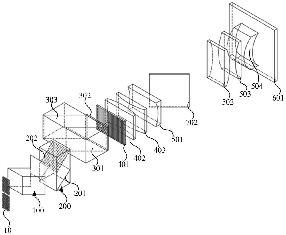
The invention provides a semiconductor laser module and an optical system, and relates to the technical field of semiconductor lasers, the semiconductor laser module comprises a semiconductor laser array, a continuous reflector and a space beam combiner, the continuous reflector and the space beam combiner are sequentially arranged in the laser beam emergent direction of the semiconductor laser array, and emergent laser beams comprise a first light beam and a second light beam which are parallel to each other; the first light beam is reflected back in the continuous reflector and then is emitted through the space beam combiner, and the second light beam enters the space beam combiner through the light incident side of the space beam combiner, forms an included angle with the first light beam, is reflected by the space beam combiner and is emitted after being combined with the first light beam; and the optical path of the first light beam in the continuous reflector is equal to the optical path of the second light beam entering the space beam combiner through the light inlet side of the space beam combiner. After the first light beam is folded back by the continuous reflector, the optical path is prolonged, and the first light beam is emitted through the space beam combiner; and the second light beam enters the space beam combiner, and the first light beam is inserted into the space beam combiner to form continuous and dense light beams. The optical path difference is zero, and the uniformity and continuity of light spots are good.

Description

technical field [0001] The present application relates to the technical field of semiconductor lasers, in particular to a semiconductor laser module and an optical system. Background technique [0002] During the propagation process of the light beam emitted by the light source, affected by optical elements and external factors, the light beam will be discontinuous, and the light will form a dead zone, which makes the formed light spot poor in continuity and uniformity. In order to solve the above problems, the usual method is to directly emit a part of the beam, and the other part of the beam will be combined with the directly emitted beam after the optical path is turned back. The beam after the optical path will be merged in the form of a slot to fill The dead zone formed by the direct outgoing beams can form continuous and dense light after combining the beams. After the same light source is split, one set of reentrants and another set of stitches combine the beams to f...

Claims


Application Information

Patent Timeline
IPC IPC(8): H01S5/00H01S5/40
CPCH01S5/005H01S5/0071H01S5/4012H01S5/4025
Inventor 蔡磊刘兴胜
Owner FOCUSLIGHT TECH
Why Eureka
Try Eureka