Active damping control method and system for buck converter constant power load system
A constant power load and damping control technology, applied in the direction of DC power input conversion to DC power output, output power conversion device, control/regulation system, etc., can solve the problems of poor damping characteristics and dynamic response characteristics, and achieve improved dynamic performance. Response, improved system damping, effects to prevent damage to the load
- Summary
- Abstract
- Description
- Claims
- Application Information
AI Technical Summary
Problems solved by technology
Method used
Image

Examples
Embodiment 1
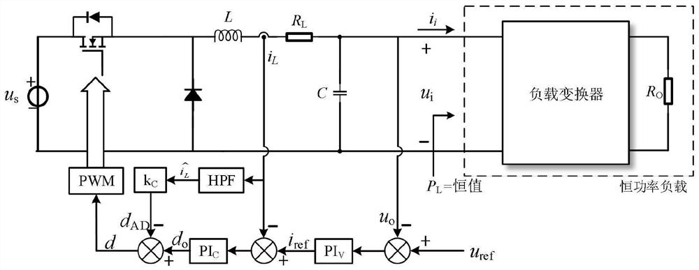
[0029] The Buck converter constant power load system includes the pre-stage Buck converter, the post-stage load converter and the load R o .
[0030] Among them, in the front stage Buck converter, u s is the input voltage, L is the filter inductance, R L is the equivalent series resistance of the inductance branch, and C is the filter capacitor.
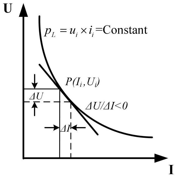
[0031] The post-stage load converter is a high-bandwidth closed-loop controlled load converter, the load converter and the load R o It can be regarded as a constant power load, and the input voltage and current characteristic curve of the subsequent load converter is as follows: figure 1 As shown, the constant power load has negative impedance characteristics, and the equivalent resistance expression under the small signal model is as follows:
[0032]
[0033] In order to solve the technical problem of poor damping characteristics and dynamic response characteristics in the existing Buck converter constant power load system c...
Embodiment 2
[0090] This embodiment provides an active damping control system for a Buck converter constant power load system. Such as Figure 9As shown, the active damping control system 200 for Buck converter constant power load system includes a signal acquisition module 201 , a voltage outer loop control module 202 , a current inner loop control module 203 , a compensation module 204 and a calculation module 205 .
[0091] Among them, the signal acquisition module 201 is used to acquire the inductor current i of the previous stage Buck converter L and capacitor voltage u o .
[0092] In the pre-stage Buck converter, u s is the input voltage, L is the filter inductance, R L is the equivalent series resistance of the inductance branch, and C is the filter capacitor. Acquire the inductance current i of the front-stage Buck converter through the signal acquisition module 201 L and capacitor voltage u o , and are respectively sent to the voltage outer loop control module 202, the cur...
PUM
 Abstract
Description
Claims
Application Information
 - R&D
- Intellectual Property
- Life Sciences
- Materials
- Tech Scout
- Unparalleled Data Quality
- Higher Quality Content
- 60% Fewer Hallucinations
Browse by: Latest US Patents, China's latest patents, Technical Efficacy Thesaurus, Application Domain, Technology Topic, Popular Technical Reports.
© 2025 PatSnap. All rights reserved.Legal|Privacy policy|Modern Slavery Act Transparency Statement|Sitemap|About US| Contact US: help@patsnap.com