
Low-power-consumption sub-sampling phase-locked loop with adaptive frequency-locked loop

A sub-sampling and self-adaptive technology, applied in the direction of reducing energy consumption, automatic power control, advanced technology, etc. The effect of avoiding static power consumption

Active Publication Date: 2021-05-28
FUDAN UNIV
View PDF12 Cites 4 Cited by
  • Summary
  • Abstract
  • Description
  • Claims
  • Application Information

AI Technical Summary

Problems solved by technology

[0003] In 2009, a new type of phase-locked loop: sub-sampling phase-locked loop was proposed as figure 2 As shown, two loops are mainly used. A traditional phase-locked loop is used to achieve frequency locking, and the other sub-sampling loop is used to achieve phase locking to achieve frequency-locked and phase-locked functions. Years of research documents and technical patents, the high-frequency phase-locked loop is mainly concentrated in the analog sub-sampling phase-locked loop, and the low-frequency band is mainly concentrated in the all-digital phase-locked loop of the sub-sampling structure. With the development of technology, the current sub-sampling lock Phase loops already have structures such as traditional SSPLL, iSSPLL, RSPLL, AMASSPLL, Type I SSPLL, CSPLL, and NPSPLL. These structures have their own characteristics in terms of power consumption, phase noise, and jitter. Some can achieve -258.9 dB FOM, and some It can achieve 50fs jitter, and some can achieve -128.1-dBc / Hz in-band absolute noise, which provides a feasible way to achieve better performance, but it has always been difficult to reduce power consumption. From traditional CPPLL to SSPLL only cuts off the current of the charge pump, so it reduces the competition between the frequency-locked loop and the sub-sampling phase-locked loop. If the frequency-locked loop and the sub-sampling loop work at the same time, the power consumption will be very large. After nearly ten years of research The literature in JSSC, the top journal of the ISSCC, found that in the implementation of many sub-sampling phase-locked loop structures, there are two parts that occupy a large amount of power consumption in the test results. One is the oscillator and the other is the frequency division in the frequency-locked loop. In many literatures, only the charge pump part of the frequency-locked loop is turned off, not the entire frequency-locked loop, especially the frequency divider, so that the power consumption of the frequency divider in high-frequency applications is still It is very large, so it is very meaningful to study how to realize a frequency-locked loop that can be turned off as a whole to reduce the high-frequency phase-locked loop. In addition, the frequency-locked loop will face There is a problem, if it can be re-locked after being disturbed by an external signal, it is a very meaningful research direction to realize a low-power adaptive frequency-locked loop
[0004] Traditional sub-sampling phase-locked loops such as figure 2 The circuit shown has two loops, a frequency-locked loop and a sub-sampling loop. The frequency is locked through the frequency-locked loop. The sub-sampling loop realizes phase-locking to ensure the frequency-locking and phase-locking of the sub-sampling PLL. After the circuit realizes frequency locking and phase locking, in order to reduce power consumption, the frequency locking loop needs to be turned off. This is realized through the PFD with dead zone, but the phase detector PFD and frequency divider in the frequency locking loop are not Shut down, which will consume a certain amount of power especially in the frequency divider in the high frequency band

Method used


Image

  • Low-power-consumption sub-sampling phase-locked loop with adaptive frequency-locked loop
  • Low-power-consumption sub-sampling phase-locked loop with adaptive frequency-locked loop
  • Low-power-consumption sub-sampling phase-locked loop with adaptive frequency-locked loop

Examples


Embodiment Construction

[0025]In order to make the purpose, technical solutions and advantages of the embodiments of the present invention clearer, the technical solutions in the embodiments of the present invention will be clearly and completely described below in conjunction with the drawings in the embodiments of the present invention. Obviously, the described embodiments It is only some embodiments of the present invention, but not all embodiments. Based on the embodiments of the present invention, all other embodiments obtained by persons of ordinary skill in the art without making creative efforts belong to the protection scope of the present invention.

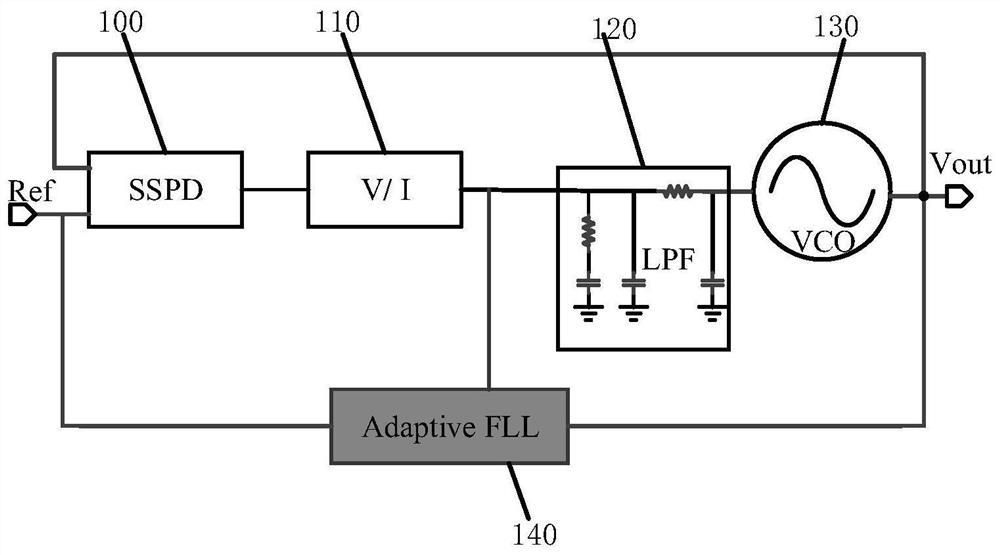
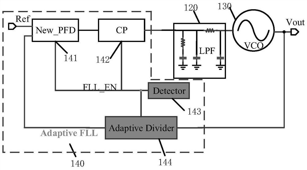
[0026] image 3 It is a specific block diagram of the implementation of the adaptive frequency-locked loop of the present invention. The low-power sub-sampling phase-locked loop with the adaptive frequency-locked loop provided by the present invention mainly combines the traditional sub-sampling phase-locked loop structure and increases the ad...


PUM


Abstract

The invention belongs to the technical field of analog radio frequency integrated circuits, and particularly relates to a low-power-consumption sub-sampling phase-locked loop with a self-adaptive frequency-locked loop. The phase-locked loop comprises a sub-sampling phase discriminator, a voltage and current conversion module, a low-pass filter, a low-power-consumption oscillator and a self-adaptive frequency-locked loop, the self-adaptive frequency-locked loop comprises a phase detection discriminator, a charge pump, a signal detection circuit and a self-adaptive frequency divider; the self-adaptive frequency-locked loop can generate an enable signal to control the turn-off and turn-on of internal modules of the self-adaptive frequency-locked loop, so that the frequency-locked loop FLL can be turned off when the whole sub-sampling phase-locked loop is locked; the circuit judges whether the phase-locked loop is locked or not according to the detected loop signal, so that the circuit generates an enable signal to determine to turn off or turn on the frequency-locked loop, and the frequency-locked loop is turned off while normal locking of the phase-locked loop is ensured, so that power consumption is reduced; when the phase-locked loop loses lock, the frequency-locked loop can be normally started, and correct frequency division and rapid locking are realized; and according to the invention, compromise between power consumption and performance of the phase-locked loop is realized.

Description

technical field [0001] The invention belongs to the technical field of analog radio frequency integrated circuits, and in particular relates to a low-power sub-sampling phase-locked loop. Background technique [0002] The phase-locked loop is one of the basic modules in the integrated circuit. It is widely used in wireless transmission receivers, transmitters, data converters and wired communications to provide the circuit with the required frequency and the local oscillator signal used to make the system work normally. , such as frequency synthesizers, clock generation circuits, clock data recovery circuits, etc., all have phase-locked loops. In recent years, with the continuous growth of data communications, the operating speed of wired and wireless systems has been pushed to tens of GHz range (each channel or each unit), which makes electronic devices and related handheld terminal devices faster and more convenient, which has a great impact on people's lifestyles, especia...

Claims


Application Information

Patent Timeline
IPC IPC(8): H03L7/08
CPCH03L7/08Y02D30/70
Inventor 纪书江闫娜闵昊
Owner FUDAN UNIV
Features
  • Generate Ideas
  • Intellectual Property
  • Life Sciences
  • Materials
  • Tech Scout
  • Unparalleled Data Quality
  • Higher Quality Content
  • 60% Fewer Hallucinations
Learn More