Liquid hydrocarbon transfer system and assembly

A technology of pump components and components, applied in the direction of charging system, pump components, engine components, etc., can solve problems such as pump operation obstruction or stop

Pending Publication Date: 2021-06-01
肯尼斯 R 瑟瑞斯
View PDF5 Cites 0 Cited by
  • Summary
  • Abstract
  • Description
  • Claims
  • Application Information

AI Technical Summary

Problems solved by technology

When debris flows into the pump, the operation of the pump may be hindered or stopped due to clogged areas of the pump

Method used


Image

  • Liquid hydrocarbon transfer system and assembly
  • Liquid hydrocarbon transfer system and assembly
  • Liquid hydrocarbon transfer system and assembly

Examples


Embodiment Construction

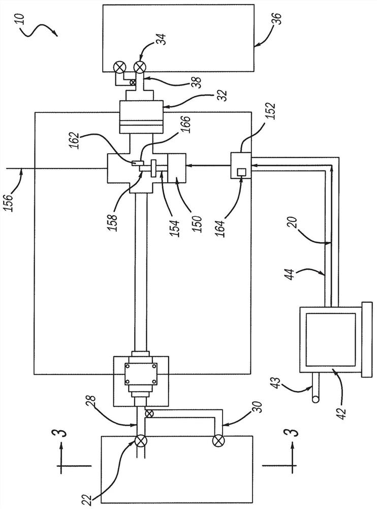
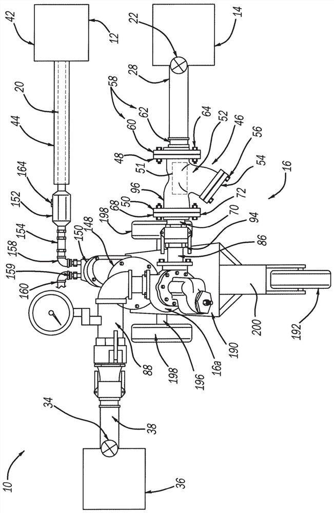
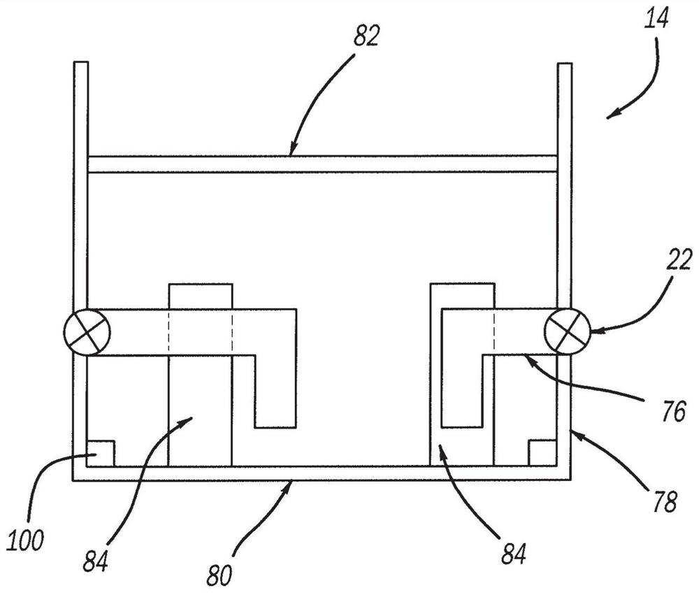
[0019] According to the present invention, the liquid hydrocarbon transfer facility 10 includes an air compressor 12 at a location preferably spaced from the storage tank 14 (i.e., outside the berm containing the storage tank 14), wherein the storage tank 14 is Tank 14 contains bulk fluid such as, for example, hydrocarbon fuel. Liquid hydrocarbon transfer pump assembly 16 is positioned proximate to storage tank 14 , preferably somewhere within the berm containing storage tank 14 . The hydrocarbon transfer pump assembly 16 is operatively connected to the air compressor 12 by an elongated air supply hose 20 . The air compressor 12 is preferably located outside of the berm housing the storage tank. The fuel transfer pump assembly 16 is connected to a first outlet valve 22 on the storage tank 14 by a main flexible hydrocarbon discharge line 28 .

[0020] The hydrocarbon transfer pump assembly 16 may also be connected to the second outlet valve 24 by an auxiliary flexible hydroca...


PUM


Abstract

A system (10) for pumping hydrocarbon bulk fluids includes an air-driven rotary or reciprocating positive displacement pump (16) in fluid communication with a tank (14) containing the hydrocarbon bulk fluid. The pump (16) contains an inlet (15) and an outlet. A filter (46) or strainer is contained within the inlet (15 for removing debris from the bulk fluid. An oiler (152) is provided for injecting an oil and / or antifreeze mixture into an air stream provided to the air-driven positive displacement pump (16). A method of pumping a bulk fluid such as a hydrocarbon fuel, from one tank to another, is also presented.

Description

technical field [0001] The present invention relates to a liquid hydrocarbon transfer assembly for moving liquid from one tank to another in a multiple storage facility. It should be understood that, as in a preferred embodiment, the fluid being transferred may be a hydrocarbon or a fuel, or it may be another bulk fluid as determined by the customer. Background technique [0002] Liquid hydrocarbons are extracted from crude oil. These hydrocarbons include kerosene, diesel for compression combustion engines, aviation fuel, heavy fuel for steam power plants, fuel for turbine engines, and fuel for gasoline engines with spark ignition systems. Each of these fuels is refined for a specific use. Each of these hydrocarbons is generally of a different grade. Some hydrocarbons vary depending on the time of year and location in the world. Additives can be mixed with hydrocarbons if desired. [0003] Liquid hydrocarbons are stored in large storage tanks until they are needed for t...

Claims


Application Information

Patent Timeline
Patent Type & Authority Applications(China)
IPC IPC(8): F02B39/02F04C23/00F16H61/48
CPCF02M37/08F02M37/0088F02M37/043F02M37/045F04C13/005F01C13/04F04C2210/203F04B23/00F04B9/12F04B15/00F04C13/002F04C2210/1044F04B17/00F04D13/04
Inventor 肯尼斯·R·瑟瑞斯
Owner 肯尼斯 R 瑟瑞斯
Why Eureka
Try Eureka