
Method for rolling ultra-thin strip based on assistance of laser energy field

An ultra-thin strip and laser technology, applied in metal rolling, metal rolling, tool manufacturing, etc., can solve the problems of unsuitable ultra-thin strip, serious oxidation degree, slow temperature rise, etc., and achieve the purpose of suppressing edge cracks and other defects Formation, refinement of recrystallization phenomena, and the effect of overcoming energy barriers

Inactive Publication Date: 2021-06-04
TAIYUAN UNIV OF TECH
View PDF14 Cites 0 Cited by
  • Summary
  • Abstract
  • Description
  • Claims
  • Application Information

AI Technical Summary

Problems solved by technology

The traditional strip heating method is not suitable for the production of ultra-thin strips due to slow temperature rise and severe oxidation.

Method used


Image

  • Method for rolling ultra-thin strip based on assistance of laser energy field
  • Method for rolling ultra-thin strip based on assistance of laser energy field

Examples


Embodiment 1

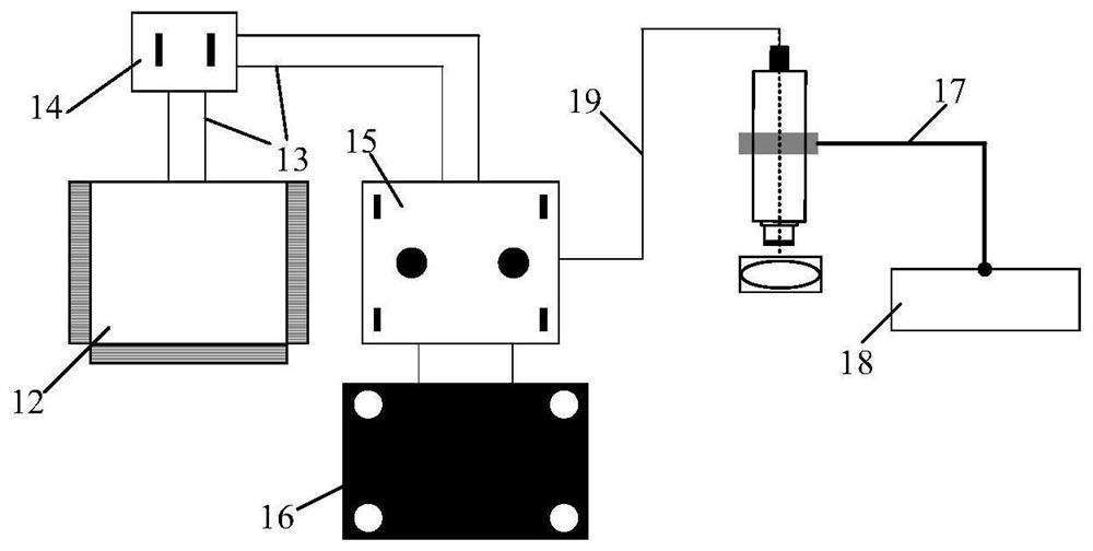
[0029] Such as figure 1 As shown, the laser energy field assisted rolling ultra-thin strip device of the present invention includes two parts, the ultra-thin strip rolling production line and the laser energy field auxiliary system, wherein the laser energy field auxiliary system is in the multi-roll mill of the ultra-thin strip rolling production line above the entrance side.

[0030] The ultra-thin strip rolling production line includes an uncoiler 1, guide rolls 2, 2', 2" (the guide rolls are used to adjust the forward direction of the ultra-thin strip and play a role in conveying), a laser emitter 3, and a focusing module 4 ( The focus module is mainly used to increase the laser energy and adjust the laser incident angle), multi-roll mill 5, ultra-thin strip cleaning device 6, nitrogen purging device 7, drying device 8, winder 9, ultrasonic assisted grinding device 11.

[0031] The laser transmitter is provided with a laser energy field auxiliary system including a contro...

Embodiment 2

[0034] In this embodiment, 304 stainless steel with a width of 50mm and a thickness of 0.05mm is used as the ultra-thin strip, the yield strength is 276Mpa, the drying device is a drying oven, and the multi-roll mill adopts a 20-roll mill;

[0035] Through the device of embodiment 1 and a method for assisting rolling an extremely thin strip based on a laser energy field, the method comprises the following steps:

[0036] Step 1. Thread the ultra-thin strip on the ultra-thin strip rolling production line. After threading, apply tension to the exit and entrance of the ultra-thin strip; the uncoiler applies post-tension, and the winder applies front tension. Appropriate tension It can reduce surface defects such as edge waves and bubble waves, improve the plastic forming ability of ultra-thin strips, and promote the flow of metal along the rolling direction; according to the yield strength of the material, the final determined tension is 70MPa;

[0037] Step 2, a laser transmitte...


PUM

PropertyMeasurementUnit
Widthaaaaaaaaaa
Thicknessaaaaaaaaaa
Focal lengthaaaaaaaaaa

Abstract

The invention discloses a method for rolling an ultra-thin strip based on assistance of a laser energy field, and belongs to the technical field of ultra-thin strip rolling. According to the method for rolling the ultra-thin strip based on the assistance of the laser energy field provided by the invention, the ultra-thin strip is heated through the assistance of the laser energy field in the ultra-thin strip rolling process of a multi-roll mill, and the ultra-thin strip is heated to the temperature higher than the material recrystallization temperature, so that the work hardening phenomenon generated in the reciprocating rolling process is reduced, edge cracks and other defects of the ultra-thin strip are restrained, the yield is increased, the quality of the ultra-thin strip is improved, and the ultra-thin strip with thinner thickness is obtained; and subsequently, an oxidation film on the surface of the ultra-thin strip is removed through an ultrasonic-assisted grinding device, and the oxidation film generated by high temperature on the surface is removed through a high-frequency excitation effect generated by ultrasonic waves. The ultra-thin strip which is thinner in thickness and better in surface quality is obtained through the method provided by the invention, and the method can be used for industrial batch production of ultra-thin strips.

Description

technical field [0001] The invention belongs to the technical field of ultra-thin strip rolling, and in particular relates to a method for assisting ultra-thin strip rolling based on a laser energy field. Background technique [0002] In recent years, with the rise of micro-manufacturing, micro-electromechanical systems and other industries, the market demand for ultra-thin tape products has grown rapidly, especially high-tech fields such as robotics and intelligent manufacturing have higher requirements for high-quality ultra-thin tape, such as for The vascular robot for vascular microtrauma diagnosis and surgery is driven by a micromotor with a diameter of 1mm, and the total length of the body is about 6mm. It will be put into the test soon. Micro air vehicles with a weight of less than 100g and an overall structural size of less than 15.24cm. The micromaterials and microdevices required in these cutting-edge fields are smaller in size and require higher precision. [00...

Claims


Application Information

Patent Timeline
IPC IPC(8): B21B1/40B21B45/00
CPCB21B1/40B21B45/004
Inventor 王振华刘元铭申宏卓王涛郝平菊李亚新陈卓然任忠凯熊晓燕王天翔
Owner TAIYUAN UNIV OF TECH
Learn More