Nondestructive cutting spray head device for solar cells

A technology of solar cells and cells, which is applied in the direction of welding/welding/cutting items, circuits, laser welding equipment, etc., can solve the problem of non-destructive cutting, reducing the mechanical properties of cells, bending strength, power loss of small cells, etc. question

Pending Publication Date: 2021-06-04
深圳光远智能装备股份有限公司
View PDF0 Cites 1 Cited by
  • Summary
  • Abstract
  • Description
  • Claims
  • Application Information

AI Technical Summary

Problems solved by technology

[0002] Before performing multi-piece series welding of solar cells, it is necessary to cut a single cell into small cells, and then perform serial welding to increase the output voltage of the module. The traditional laser cutting method will cause a certain heat-affected area in the cutting area. There are micro cracks, which will cause slag, reduce the mechanical properties (including bending strength) of the cell, and reduce the power generation of the cell
[0003] The battery laser cutting equipment in the prior art uses the first slotting laser to cut the front of the battery to a certain depth, and then the second laser heats the groove opened by the first laser, so that the battery is cracked by heat, and There is no water cooling during the whole cutting process, so the small pieces of cut cells will still have a part of power loss, so that the real lossless cutting can not be achieved. At the same time, since no cooling water is used in the cutting process, the Generate a large amount of dust, which will cause pollution to the working environment

Method used


Image

  • Nondestructive cutting spray head device for solar cells
  • Nondestructive cutting spray head device for solar cells
  • Nondestructive cutting spray head device for solar cells

Examples


Embodiment Construction

[0024] The technical solutions of the present invention will be described below in conjunction with the accompanying drawings and embodiments.

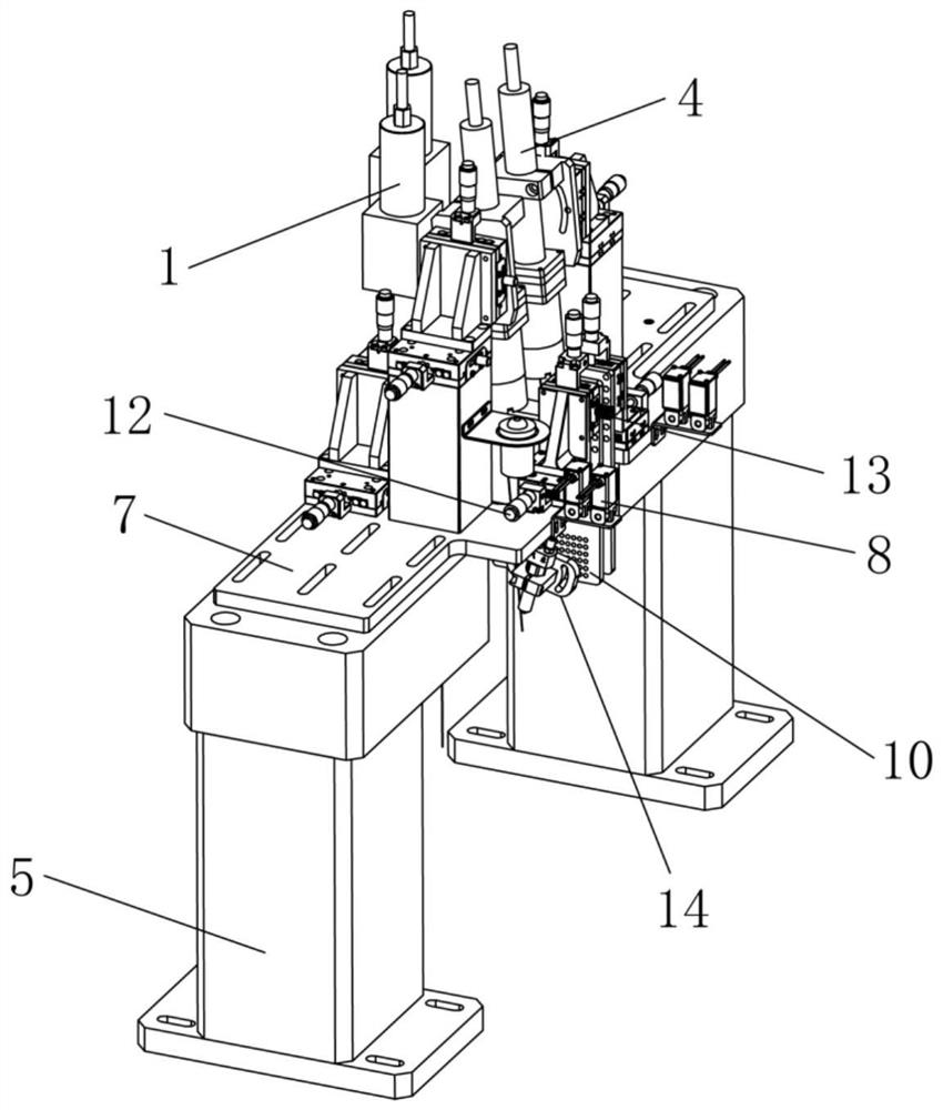
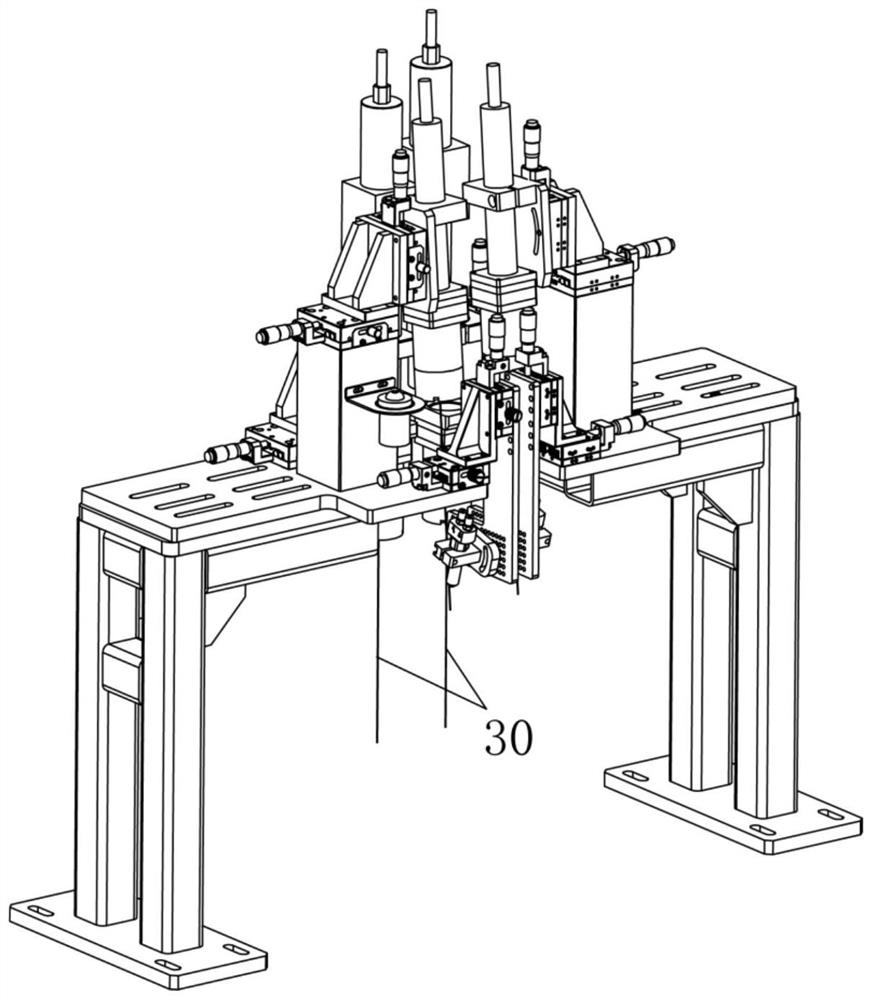
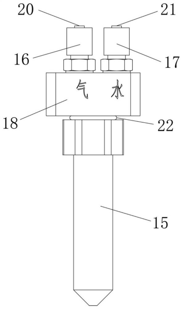
[0025] like Figure 1 to Figure 4 As shown, a non-destructive cutting nozzle device for solar cells according to the present invention includes a machine platform 7 on which a laser 30 for cutting cells and a nozzle assembly 10 for cooling cells are provided. The nozzle assembly 10 includes Nozzle 15, air inlet pipe 16 and water inlet pipe 17, air inlet pipe 16 and water inlet pipe 17 are connected to nozzle 15 through air-water joint 18, nozzle 19 is provided in nozzle 15, nozzle 19 and laser 30 corresponding settings, air inlet pipe 16 is provided with The air inlet 20 is connected to the nozzle 19 through the air inlet passage, and the water inlet 21 is arranged on the water inlet pipe 17, and the water inlet 21 is connected to the nozzle 19 through the water inlet passage. The above constitutes the basic structure of the present ...


PUM


Abstract

The invention relates to the technical field of battery pieces, in particular to a nondestructive cutting spray head device for solar cells. The device comprises a machine table, the machine table is provided with laser used for cutting the battery pieces and a spray head assembly used for cooling the battery pieces, the spray head assembly comprises a spray head, an air inlet pipe and a water inlet pipe, and the air inlet pipe and the water inlet pipe are connected to the spray head through air-water connectors. A nozzle is arranged in the spray head and corresponds to the laser, an air inlet is formed in the air inlet pipe and connected to the nozzle through an air inlet channel, and a water inlet is formed in the water inlet pipe and connected to the nozzle through a water inlet channel. By the adoption of the structural arrangement, in the laser cutting process for cutting the battery pieces, cooling water is sprayed out through the spray head of the spray head assembly to cool the battery pieces, so that the cut small solar cells are free of power loss, better in cutting quality and truly nondestructive, meanwhile, a large amount of dust can be prevented from being generated in the cutting process, and higher environmental friendliness is achieved.

Description

technical field [0001] The invention relates to the technical field of solar cells, in particular to a non-destructive cutting nozzle device for solar cells. Background technique [0002] Before performing multi-piece series welding of solar cells, it is necessary to cut a single cell into small cells, and then perform serial welding to increase the output voltage of the module. The traditional laser cutting method will cause a certain heat-affected area in the cutting area. There are micro-cracks, which will generate slag, reduce the mechanical properties (including bending strength) of the battery sheet, and reduce the power generation power of the battery sheet. [0003] The battery laser cutting equipment in the prior art uses the first slotting laser to cut the front of the battery to a certain depth, and then the second laser heats the groove opened by the first laser, so that the battery is cracked by heat, and There is no water cooling during the whole cutting proce...

Claims


Application Information

Patent Timeline
IPC IPC(8): B23K26/14B23K26/142B23K26/364B23K26/402B23K101/40
CPCB23K26/14B23K26/402B23K26/142B23K26/1437B23K26/1462B23K26/364B23K2101/40B23K2103/56
Inventor 朱光江北
Owner 深圳光远智能装备股份有限公司
Why Eureka
Try Eureka