Automatic plane correction method for intelligent tube plate welding robot based on cross laser

A welding robot and cross laser technology, applied in welding equipment, auxiliary welding equipment, welding/cutting auxiliary equipment, etc., to achieve the effect of improving image processing speed, avoiding external light source interference, and high calculation accuracy

Inactive Publication Date: 2021-06-04
常州英迈乐智能系统有限公司
View PDF13 Cites 4 Cited by
  • Summary
  • Abstract
  • Description
  • Claims
  • Application Information

AI Technical Summary

Problems solved by technology

[0003] The purpose of the present invention is to provide an automatic plane correction method for a tube-sheet intelligent welding robot based on a cross laser, so as to solve the problem that the accurate robot end attitude leveling cannot be truly realized in the above-mentioned background technology

Method used


Image

  • Automatic plane correction method for intelligent tube plate welding robot based on cross laser
  • Automatic plane correction method for intelligent tube plate welding robot based on cross laser
  • Automatic plane correction method for intelligent tube plate welding robot based on cross laser

Examples


Embodiment

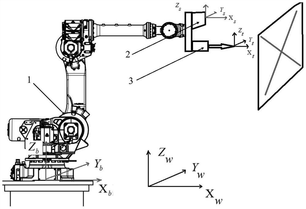
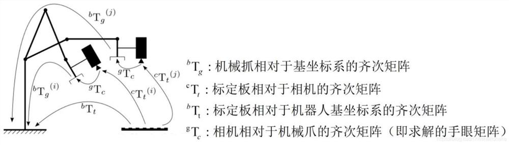
[0031] see Figure 1-3 , the present invention provides a technical solution: an automatic plane correction method for a tube-sheet intelligent welding robot based on a cross laser, comprising the following steps:

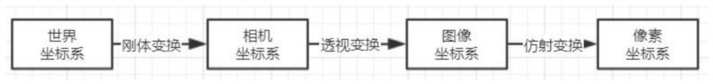
[0032] Step 1: Sensor Calibration, see figure 1 , after the installation of the cross laser three-dimensional measurement sensor 2 is completed, the internal parameters of the camera need to be calibrated, and the internal parameter matrix and distortion parameters of the camera can be obtained. The pictures taken by the camera still have certain distortions, including barrel distortion and pincushion distortion. The model includes radial distortion and tangential distortion, and the radial distortion formula is The formula for tangential distortion is Respectively, the ideal undistorted normalized image coordinates and the distorted normalized image coordinates are the distance from the image pixel to the image center point, namely r 2 =x 2 +y 2 . The seco...


PUM


Abstract

The invention belongs to the technical field of industrial welding, and particularly relates to an automatic plane correction method for an intelligent tube plate welding robot based on a cross laser. The method comprises the steps of sensor calibration, system hand-eye calibration, light strip center extraction and robot attitude angle deviation calculation. According to the method, the cross laser is directly projected to a tube plate plane to obtain three-dimensional data without being affected by the placement angle of the tube plate plane, so that the degree of freedom is larger; by adopting a gradual iteration approximation mode, the leveling precision can be well guaranteed, and the manual participation degree is greatly reduced; by means of iterative leveling, an ICP iterative algorithm based on the least square method is adopted in each leveling calculation, calculation results are converted into Euler angles, higher calculation precision is achieved, the leveling precision angle error is about 0.1 degree, and the method is suitable for most robot controllers and has high generalization performance.

Description

technical field [0001] The invention relates to the technical field of industrial welding, in particular to an automatic plane correction method for a tube plate intelligent welding robot based on a cross laser. Background technique [0002] Industrial robot alignment technology is the technical basis for industrial robots to realize docking, assembly, grasping, drilling and other functions. To realize the alignment of industrial robots, two methods are usually used: the first is to adjust the end effector of the industrial robot to reach the same fixed position with a fixed posture each time by means of teaching or offline programming. By adjusting the pose of the workpiece, Align with the end effector of the industrial robot; the second is to install a pose measurement sensor on the end of the industrial robot, and adjust the attitude of the end effector of the industrial robot and align it with the workpiece by measuring the position and attitude of the workpiece. The fo...

Claims


Application Information

Patent Timeline
Patent Type & Authority Applications(China)
IPC IPC(8): B23K37/00B25J19/02
CPCB23K37/00B25J19/02B25J19/022
Inventor 王国强
Owner 常州英迈乐智能系统有限公司
Why Eureka
Try Eureka