Prefabricated composite beam-column joint and its construction method based on uhpc

A beam-column joint and assembled technology, which is applied in the direction of columns, girders, joists, etc., can solve the problems of affecting the pouring quality of the post-casting area of ​​the joints, demanding construction accuracy, inconvenient transportation and installation, etc.

Active Publication Date: 2022-04-29
TSINGHUA UNIV
View PDF17 Cites 0 Cited by
  • Summary
  • Abstract
  • Description
  • Claims
  • Application Information

AI Technical Summary

Problems solved by technology

The post-cast monolithic prefabricated concrete frames widely used at present mainly have the following deficiencies: (1) Beam-column joints in high-intensity areas need to be equipped with dense stirrups at the beam ends, column ends, and joint core areas, and the bottom reinforcement of bidirectional frame beams The need for anchorage in the joint area leads to difficulties in on-site construction; (2) the longitudinal reinforcement of the column needs to be connected by sleeves above the joint area, which requires strict construction accuracy and further increases the difficulty of construction; (3) prefabricated components often have a large number of steel bars exposed, resulting in Transportation and installation are inconvenient; (4) The steel bars in the post-casting area of ​​the node are dense, which affects the pouring quality of the post-casting area of ​​the node

Method used


Image

  • Prefabricated composite beam-column joint and its construction method based on uhpc
  • Prefabricated composite beam-column joint and its construction method based on uhpc
  • Prefabricated composite beam-column joint and its construction method based on uhpc

Examples


Embodiment Construction

[0040] In order to make the above objects, features and advantages of the present invention more comprehensible, specific implementations of the present invention will be described in detail below in conjunction with the accompanying drawings. In the following description, numerous specific details are set forth in order to provide a thorough understanding of the present invention. However, the present invention can be implemented in many other ways different from those described here, and those skilled in the art can make similar improvements without departing from the connotation of the present invention, so the present invention is not limited by the specific embodiments disclosed below.

[0041] In describing the present invention, it should be understood that the terms "center", "longitudinal", "transverse", "length", "width", "thickness", "upper", "lower", "front", " Back", "Left", "Right", "Vertical", "Horizontal", "Top", "Bottom", "Inner", "Outer", "Clockwise", "Counte...


PUM


Abstract

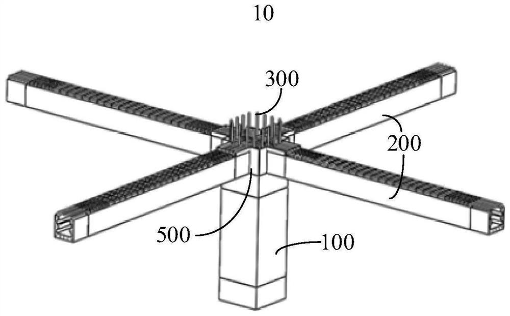
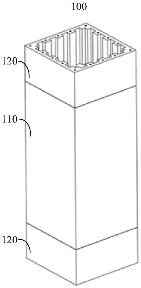
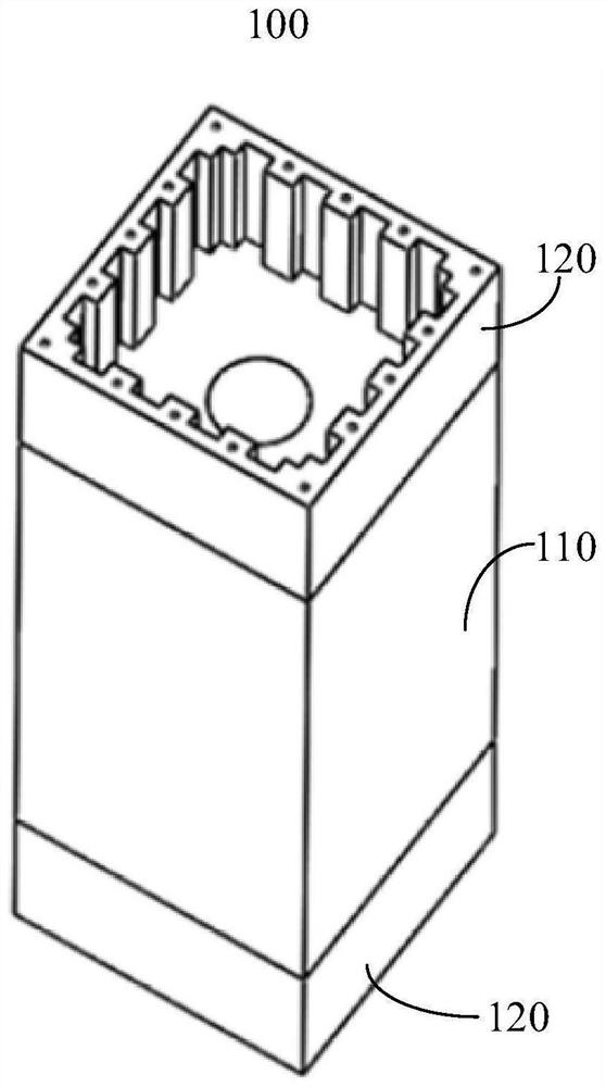
The invention relates to a UHPC-based assembled composite beam-column node and a construction method thereof. The prefabricated composite beam-column node based on UHPC includes prefabricated column, prefabricated beam and post-casting area of ​​the node. The mechanical properties of the column end of the prefabricated column are higher than those of the column middle. The mechanical properties of the beam end of the prefabricated beam are higher than that of the beam middle. The longitudinal lapping reinforcement in the post-casting area of ​​the node is connected to the end of the column by pouring, and the transverse lapping reinforcement is connected to the end of the beam by pouring. In the above UHPC-based prefabricated composite beam-column joint and its construction method, there is no need to set stirrups for strengthening the structural strength in the post-casting area of ​​the joint, beam end and column end. The lap length of longitudinal reinforcement of precast beams and precast columns can be greatly reduced compared with ordinary concrete. The longitudinal reinforcement of the prefabricated column does not need to be connected by sleeves. The upper reinforcement of prefabricated columns and prefabricated beams is hardly exposed. The prefabricated composite beam-column joint based on UHPC of the present invention is convenient to construct, and the amount of concrete with higher mechanical properties (such as ultra-high performance concrete) is less, and has good comprehensive economic benefits and anti-seismic performance.

Description

technical field [0001] The invention relates to the technical field of building structures, in particular to a UHPC-based assembled composite beam-column node and a construction method thereof. Background technique [0002] Reinforced concrete (RC) frame structures have the advantages of easy space separation, light weight, and flexible building layout, and are widely used in multi- and high-rise public buildings that undertake important social functions such as office buildings, hospitals, and teaching buildings. The post-cast monolithic prefabricated concrete frames widely used at present mainly have the following deficiencies: (1) Beam-column joints in high-intensity areas need to be equipped with dense stirrups at the beam ends, column ends, and joint core areas, and the bottom reinforcement of bidirectional frame beams The need for anchorage in the joint area leads to difficulties in on-site construction; (2) the longitudinal reinforcement of the column needs to be conn...

Claims


Application Information

Patent Timeline
Patent Type & Authority Patents(China)
IPC IPC(8): E04B1/21E04G21/00E04C3/20E04C3/34E04B5/17
CPCE04B1/21E04G21/00E04C3/20E04C3/34E04B5/17
Inventor 丁然聂鑫张子煜樊健生
Owner TSINGHUA UNIV
Why Eureka
Try Eureka