
Gas compressor and handheld dust collector

A compressor and pressure sensor technology, applied in vacuum cleaners, machines/engines, mechanical equipment, etc., can solve the problems of high wind noise, narrow high-efficiency fan working area, increased fan diameter and volume, etc., to achieve low operating wind noise, Small size and high work efficiency

Pending Publication Date: 2021-06-04
INATSU ELECTRIC (ZHUHAI) CO LTD
View PDF0 Cites 0 Cited by
  • Summary
  • Abstract
  • Description
  • Claims
  • Application Information

AI Technical Summary

Problems solved by technology

[0004] The purpose of the present invention is to overcome the shortcomings of the above-mentioned prior art, and provide a compressor and a hand-held vacuum cleaner, which solve the problem of increasing the air power and increasing the suction volume of the fan in the prior art, which causes the diameter and volume of the fan to increase, Problems of high wind noise and narrow working efficiency area of ​​fan

Method used


Image

  • Gas compressor and handheld dust collector
  • Gas compressor and handheld dust collector
  • Gas compressor and handheld dust collector

Examples


Embodiment 1

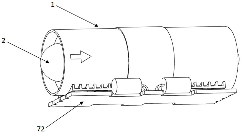
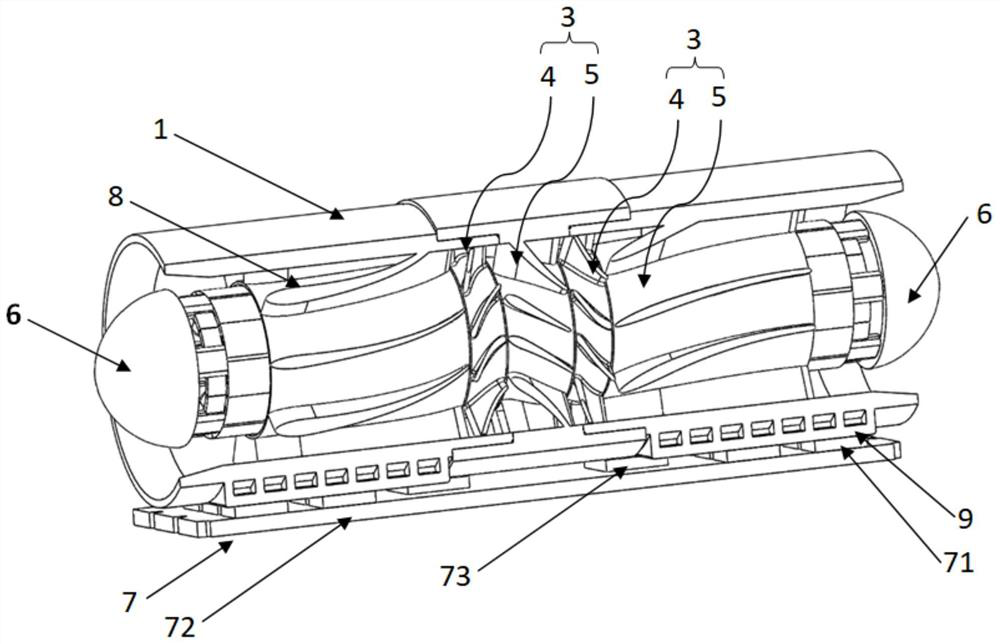
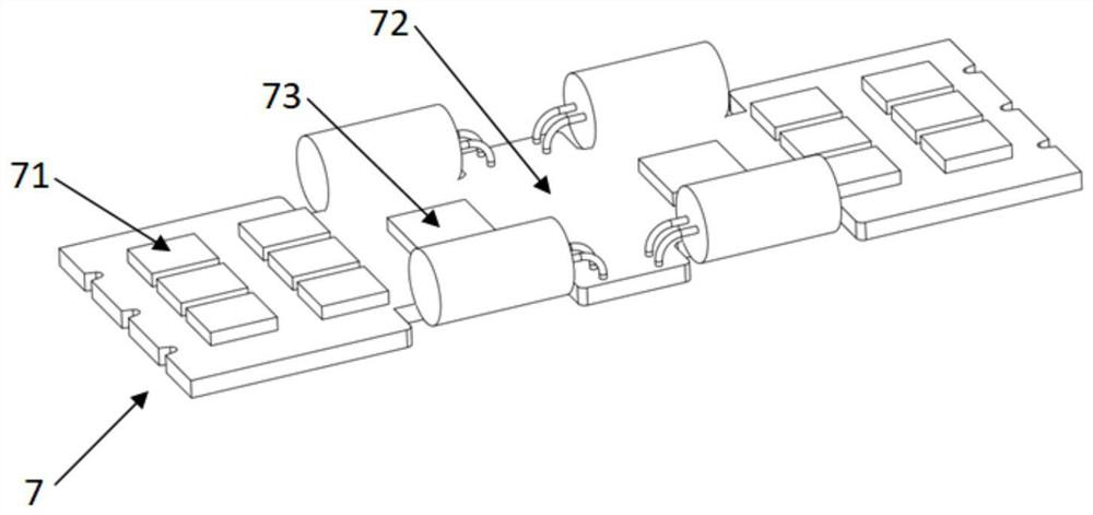
[0042] refer to Figure 5 , as an example, in this embodiment, an axial-flow compressor is provided. This compressor is an axial-flow compressor, which includes two stages of moving and stationary blade units, which are respectively the first stage of moving and stationary blade units 31 and the second stage of The moving and stationary vane unit 32, the guide vane, the first stage of the moving and stationary vane unit 31 and the second stage of the moving and stationary vane unit 32 are arranged in sequence along the airflow direction, and the housing includes the first housing 11, the second housing 12 and the connecting housing 13 , the first-stage moving and stationary blade unit 31 includes a first-stage moving blade 311 and a first-stage stationary blade 312 , the second-stage moving and stationary blade unit 32 includes a second-stage moving blade 321 and a second-stage stationary blade 322 , and the guide vanes are connected to The inner wall of the first housing 11, ...

Embodiment 2

[0046] refer to Figure 6 , as an example, in this embodiment, a mixed-flow compressor is provided, the compressor is a mixed-flow compressor, in which the first-stage moving blade 3110 and the second-stage moving blade 3210 both adopt the structure of a mixed-flow fan, For other structures, refer to the above-mentioned embodiment 1, and details are not repeated here. Similarly, the moving blades with the structure of the mixed-flow fan also have the characteristics of large air volume, small motor outer diameter, small volume, low operating speed, low operating wind noise, widening the efficient working area of ​​the vacuum cleaner, and high working efficiency.

[0047] Of course, according to the actual situation, axial flow and mixed flow blades can be used in combination, that is, the form of the first-stage axial flow blade and the first-stage mixed flow blade. In addition, centrifugal type blades can also be used in this inventive idea.

[0048] In the second aspect of ...


PUM


Abstract

The invention provides a gas compressor. The gas compressor comprises a shell, a power module and at least two stages of moving and static blade units; the moving and static blade units are coaxially arranged; each stage of moving and static blade unit comprises a moving blade and a static blade, and the moving blade and the static blade are coaxially arranged and are in clearance fit; the moving blades and the static blades of the adjacent stages of moving and static blade units are in clearance fit in sequence; the moving blades are in transmission connection with the power module, and the moving and static blade units and the power module are arranged in the shell. The invention further provides a handheld dust collector comprising the gas compressor. The at least two stages of moving and static blade units are coaxially arranged and are connected in series, the moving blades and the static blades of the moving and static blade units are sequentially in clearance fit, each stage of moving blade is driven by the corresponding power unit, and the gas compressor has the characteristics that the air volume is large, the outer diameter of the motor is small, the size is small, the operation rotating speed is low, the operation air noise is low, the efficient working area of the dust collector is widened, and the working efficiency is high.

Description

technical field [0001] The invention belongs to the technical field of household appliances, in particular to an air compressor and a hand-held vacuum cleaner. Background technique [0002] Vacuum cleaners can be divided into vertical, horizontal and hand-held according to their structure. The working principle of the vacuum cleaner is to use the motor to drive the blades to rotate at high speed, generate air negative pressure in the sealed housing, and absorb dust. And with the increasing demand of people's life, the air power requirements of the vacuum cleaner are getting higher and higher. [0003] At present, in the pursuit of larger air volume and greater suction in the existing small household handheld vacuum cleaners, in order to maximize the air power, it is often necessary to increase the diameter of the impeller or increase the speed of the impeller. In this way, the strength of the impeller material Higher requirements lead to an increase in material costs, and ...

Claims


Application Information

Patent Timeline
Patent Type & Authority Applications(China)
IPC IPC(8): F04D19/02F04D29/32F04D29/54F04D25/08F04D27/00F04D29/66F04D29/58F04D29/52A47L5/24A47L9/00
CPCA47L5/24A47L9/00F04D19/02F04D25/08F04D27/00F04D27/001F04D29/321F04D29/522F04D29/542F04D29/584F04D29/666
Inventor 张震坚庞广陆
Owner INATSU ELECTRIC (ZHUHAI) CO LTD
Features
  • Generate Ideas
  • Intellectual Property
  • Life Sciences
  • Materials
  • Tech Scout
  • Unparalleled Data Quality
  • Higher Quality Content
  • 60% Fewer Hallucinations
Learn More