Solar photovoltaic and air source heat pump combined water heater
An air source heat pump and solar photovoltaic technology, applied in water heaters, fluid heaters, refrigeration components, etc., can solve the problems of low heat exchange efficiency of heat pump units, evaporator frosting, heat pump units cannot operate, etc., to achieve high efficiency utilization, The effect of expanding the applicable area
- Summary
- Abstract
- Description
- Claims
- Application Information
AI Technical Summary
Problems solved by technology
Method used
Image
Examples
Embodiment 1
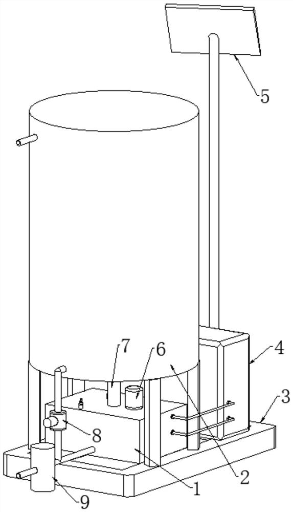
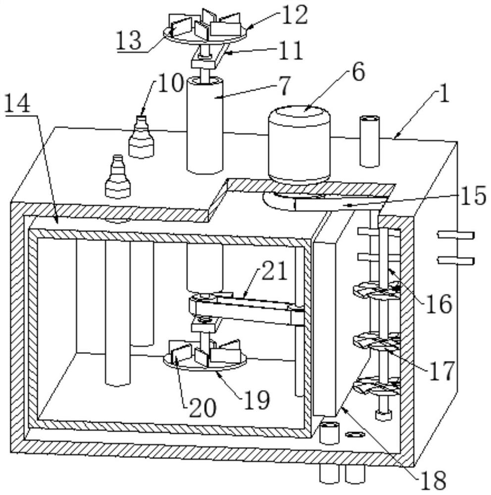
[0030] refer to Figure 1 to Figure 9 , a combined solar photovoltaic and air source heat pump water heater, including a heat pump host 4, a condenser 31, an evaporator 18, a bottom frame 3, a water storage tank 2, a photovoltaic panel 5, an electromagnetic water valve 8 and a water tank 1, a heat pump host 4 and The water storage tank 2 is installed on the upper end of the bottom frame 3, the center of the lower end of the water storage tank 2 is fixedly connected with a sleeve 7 through a round hole, and the upper end of the water tank 1 is fixedly connected with the pipe wall of the sleeve pipe 7 through a through hole. The interior is fixedly connected with an inner tank 14, the lower end of the sleeve 7 runs through the side wall of the inner tank 14 and extends into the inner tank 14, the upper end of the water tank 1 is fixedly connected with two electric heating rods 10, and the lower ends of the two electric heating rods 10 It runs through the upper end of the inner c...
Embodiment 2
[0032] Embodiment 2: the difference based on Embodiment 1 is;
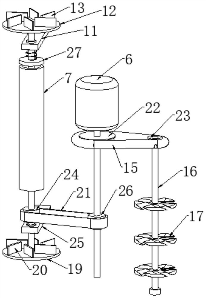
[0033] refer to Figure 2 to Figure 5 , the mixing mechanism includes a first synchronous wheel 24 fixed on the shaft wall of the transmission shaft 29, and the first synchronous wheel 24 is located in the inner container 14, and the second synchronous wheel 26 is fixedly connected to the shaft wall of the rotating shaft, and the first synchronous wheel 24 A synchronous belt 21 is wound together with the second synchronous wheel 26, and the upper end of the transmission shaft 29 extends into the water storage tank 2 and is fixedly connected with a disc 12, and the upper end of the disc 12 is fixedly connected with a plurality of inclined mixers. The water blade 13 is fixedly connected with the support rod 11 in the water storage tank 2, and the rod wall of the support rod 11 is rotatably connected with the shaft wall of the transmission shaft 29 through the second rolling bearing, and the lower end of the transmis...
Embodiment 3
[0036] Embodiment 3: the difference based on embodiment 1 is;
[0037] refer to Figure 6 to Figure 9 The filter mechanism includes a rubber block 34 arranged in the housing 9, and a liquid passage is opened between the opposite sides of the rubber block 34, and the side wall of the rubber block 34 is slidingly sleeved with two symmetrical distribution channels through a rectangular through hole. The upper ends of the two rectangular rods 32 are fixedly connected to the inner wall of the upper end of the housing 9, the housing 9 is provided with a limit rod, and the lower end of the rectangular rod 32 passes through the rectangular through hole and is connected to the rod wall of the limit rod. Fixedly connected, the rod wall of the rectangular rod 32 is slidably sleeved with a second spring 33, the upper end of the second spring 33 is fixedly connected with the upper end inner wall of the housing 9, and the lower end of the second spring 33 is fixedly connected with the upper...
PUM
 Abstract
Description
Claims
Application Information
 - R&D
- Intellectual Property
- Life Sciences
- Materials
- Tech Scout
- Unparalleled Data Quality
- Higher Quality Content
- 60% Fewer Hallucinations
Browse by: Latest US Patents, China's latest patents, Technical Efficacy Thesaurus, Application Domain, Technology Topic, Popular Technical Reports.
© 2025 PatSnap. All rights reserved.Legal|Privacy policy|Modern Slavery Act Transparency Statement|Sitemap|About US| Contact US: help@patsnap.com


