Image acquisition system and method based on gear shaft visual detection, product, equipment and terminal

An image acquisition system and visual inspection technology, applied in measurement devices, optical testing of flaws/defects, material analysis by optical means, etc., can solve problems such as unfavorable inspection and statistics, no data preservation, inconsistency, etc., to save visual inspection. Required calculation examples, easy design and spatial arrangement, the effect of reducing the number of cameras and light sources

Pending Publication Date: 2021-06-04
菲特(天津)检测技术有限公司
View PDF5 Cites 3 Cited by
  • Summary
  • Abstract
  • Description
  • Claims
  • Application Information

AI Technical Summary

Problems solved by technology

[0010] 1) High inspection cost and low efficiency: The inspection process requires the full participation of inspectors, which is time-consuming and laborious;
[0011] 2) Poor stability and many missed detections: there are problems such as missed detections and inconsistent individual judgments;
[0012] 3) Difficult to trace the source: After the human eye inspection is completed, there is no saved data, which is not conducive to future inspection and statistics;
[0014] Therefore, the manual quality inspection method can no longer meet the current factory development needs. An optical design system that can automatically detect surface defects of gear shafts is urgently needed to reduce labor intensity, maintenance costs and potential risks; improve shooting accuracy and detection speed. The surface to be tested will not cause damage

Method used


Image

  • Image acquisition system and method based on gear shaft visual detection, product, equipment and terminal
  • Image acquisition system and method based on gear shaft visual detection, product, equipment and terminal
  • Image acquisition system and method based on gear shaft visual detection, product, equipment and terminal

Examples


Embodiment Construction

[0070] In order to make the above objects, features and advantages of the present invention more comprehensible, specific implementations of the present invention will be described in detail below in conjunction with the accompanying drawings. In the following description, numerous specific details are set forth in order to provide a thorough understanding of the present invention. However, the present invention can be implemented in many other ways different from those described here, and those skilled in the art can make similar improvements without departing from the connotation of the present invention, so the present invention is not limited by the specific implementations disclosed below.

[0071] It should be noted that when an element is referred to as being “fixed” to another element, it can be directly on the other element or there can also be an intervening element. When an element is referred to as being "connected to" another element, it can be directly connected ...


PUM

PropertyMeasurementUnit
lengthaaaaaaaaaa

Abstract

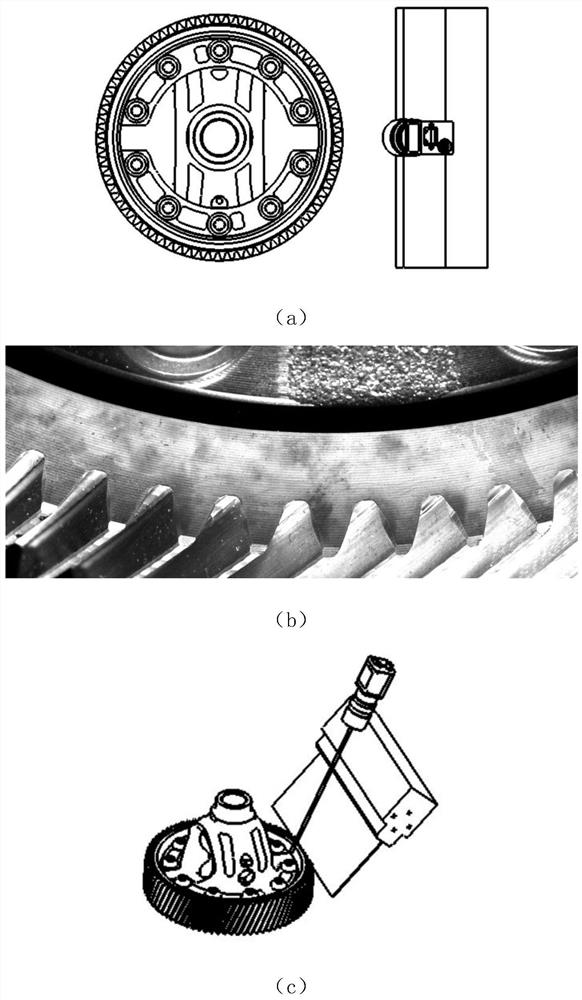
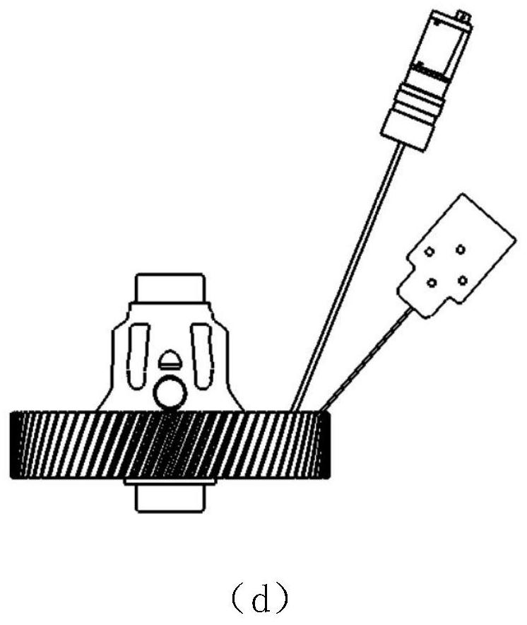
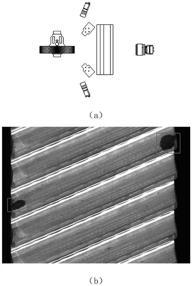
The invention discloses an image acquisition system and method based on gear shaft visual detection, a product, equipment and a terminal, and relates to the technical field of gear shaft product defect detection and visual optical design. A shooting station is arranged, the upper and lower end surfaces and the upper and lower tooth surfaces of a gear shaft respectively use a set of independent shooting units which are respectively used for detecting surface defects of the upper and lower end surfaces and the upper and lower tooth surfaces of the gear shaft; end surface shooting units are arranged, the shooting units shooting the upper and lower end surfaces are mirror images of each other along the tooth surfaces, and the upper and lower end surface areas of the gear are shot; tooth surface shooting units are arranged, the shooting units shooting the upper and lower tooth surfaces are mirror images of each other along the axis of the gear, and the upper and lower tooth surface areas are shot. According to the optical design system, the picture information of each surface of the gear shaft is effectively collected, the number of cameras and light sources is reduced, mechanical motion scheme design is facilitated, and potential risks and equipment maintenance cost are reduced. When the optical design system is implemented, an original gear shaft production line does not need to be broken, and shooting can be completed only by stopping on the original production line.

Description

technical field [0001] The disclosure of the present invention relates to the technical field of gear shaft product defect detection and visual optical design, and in particular to an image acquisition system, method, product, device, and terminal based on gear shaft visual detection. Background technique [0002] Gear materials for automotive gearboxes not only have good strength, toughness, and wear resistance, but also require small deformation and high machining accuracy. In the heat treatment process of gears, in addition to general quenching and tempering, various surface hardening processes such as carburizing and quenching, nitriding treatment, and high-frequency quenching are also used. The technical requirements for gear materials are: [0003] 1) Sufficient core hardenability, surface hardness and deep layer, and ensure that the carburized layer and core do not appear supercooled austenite decomposition products during carburizing and quenching of gears; [0004...

Claims


Application Information

Patent Timeline
Patent Type & Authority Applications(China)
IPC IPC(8): G01N21/88G01N21/95
CPCG01N21/8851G01N21/8806G01N21/9515
Inventor 胡江洪王敏雪袁帅鹏郑君辉周学博刘杨
Owner 菲特(天津)检测技术有限公司
Why Eureka
Try Eureka