High-temperature waste gas purification equipment

A technology for purifying equipment and high-temperature exhaust gas, which is applied in gas treatment, chemical instruments and methods, and dispersed particle filtration, etc. It can solve the problems of increasing atmospheric temperature, reducing the efficiency of exhaust gas treatment equipment, dust adhesion, etc., and achieves volume expansion. Effect

Inactive Publication Date: 2021-06-08
费红泉
View PDF0 Cites 2 Cited by
  • Summary
  • Abstract
  • Description
  • Claims
  • Application Information

AI Technical Summary

Problems solved by technology

[0003] When purifying high-temperature waste gas, the waste gas is sent to the inside of the treatment chamber for reaction treatment. During the treatment process, because the industrial waste gas contains a large amount of sulfur dioxide, the equipment cannot fully absorb the sulfur dioxide in the waste gas. If the waste gas is directly discharged into the air, the sulfur dioxide remaining in the exhaust gas will spread in the air, which will increase the temperature of the atmosphere and cause more serious environmental pollution, and the dust impurities generated after the exhaust gas treatment will accumulate inside the equipment. Under the action of high temperature, there will be high humidity, which will cause dust to adhere to the inside of the equipment, which will easily cause peculiar smell inside the equipment, requiring secondary treatment by the staff, reducing the efficiency of waste gas treatment and the use effect of the equipment

Method used


Image

  • High-temperature waste gas purification equipment
  • High-temperature waste gas purification equipment
  • High-temperature waste gas purification equipment

Examples


Embodiment 1

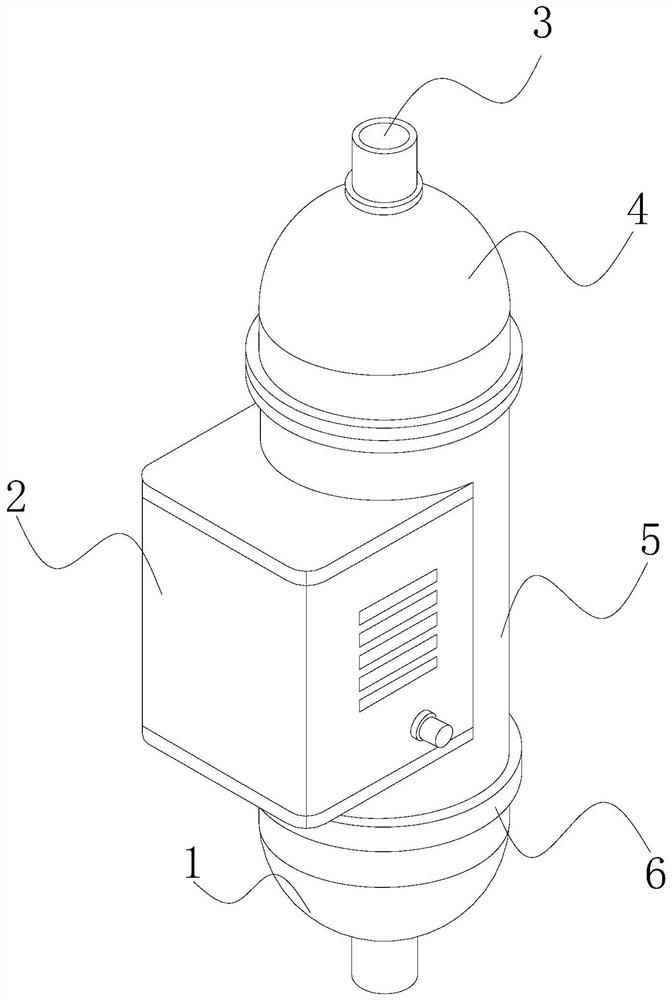
[0031] see figure 1 , the present invention provides a technical solution: a high-temperature exhaust gas purification equipment, the structure of which includes a discharge chamber 1, a fan 2, an inlet and outlet 3, a removal device 4, a purification chamber 5, and a body 6, and the discharge chamber 1 is arranged on the body 6 At the bottom, the end of the body 6 away from the discharge chamber 1 is connected to the removal device 4, the removal device 4 and the end of the discharge chamber 1 away from the body 6 are provided with an inlet and outlet 3, and the middle position of the body 6 is installed A clean chamber 5, a fan 2 is connected to one side of the clean chamber 5, and the fan 2 is connected to the body 6 through wires.

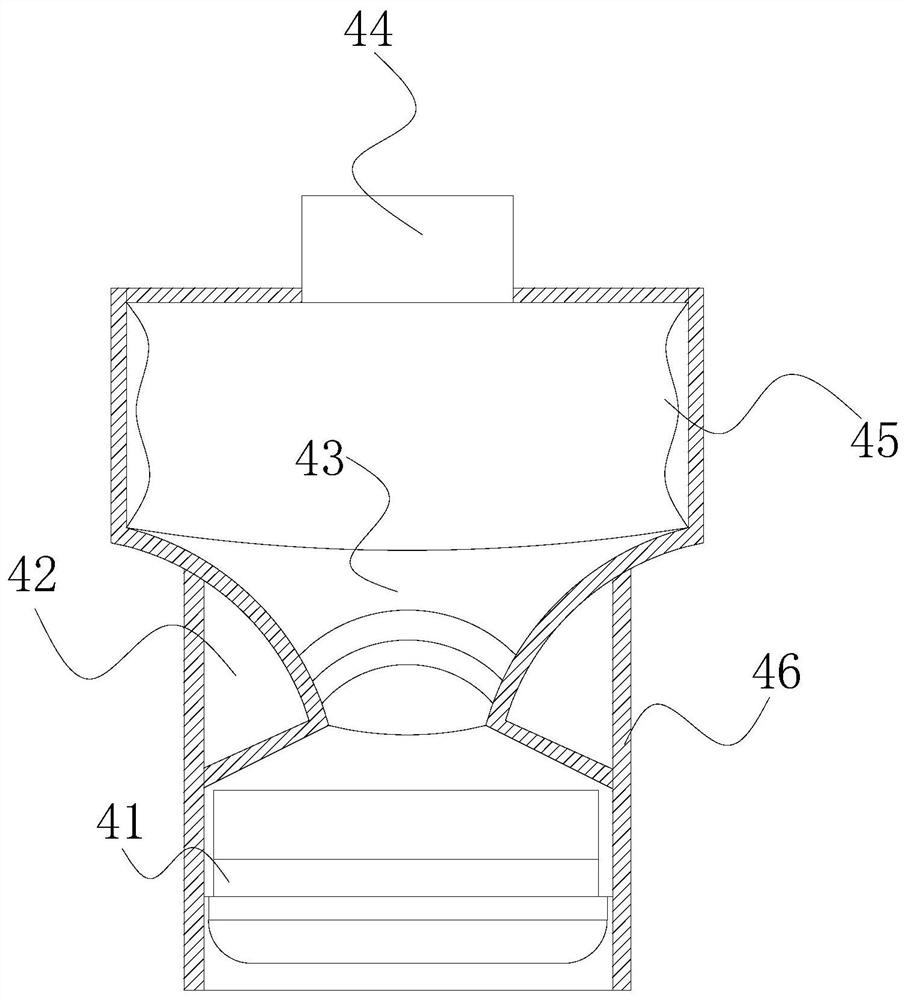
[0032] see figure 2 , the removal device 4 includes a desulfurization assembly 41, a partition 42, an adsorption tank 43, an interface 44, a receiving chamber 45, and a body 46, the desulfurization assembly 41 is arranged at the bottom of th...

Embodiment 2

[0042] see figure 1 , the present invention provides a technical solution: a high-temperature exhaust gas purification equipment, the structure of which includes a discharge chamber 1, a fan 2, an inlet and outlet 3, a removal device 4, a purification chamber 5, and a body 6, and the discharge chamber 1 is arranged on the body 6 At the bottom, the end of the body 6 away from the discharge chamber 1 is connected to the removal device 4, the removal device 4 and the end of the discharge chamber 1 away from the body 6 are provided with an inlet and outlet 3, and the middle position of the body 6 is installed A clean chamber 5, a fan 2 is connected to one side of the clean chamber 5, and the fan 2 is connected to the body 6 through wires.

[0043] see figure 2 , the removal device 4 includes a desulfurization assembly 41, a partition 42, an adsorption tank 43, an interface 44, a receiving chamber 45, and a body 46, the desulfurization assembly 41 is arranged at the bottom of th...


PUM


Abstract

The invention discloses high-temperature waste gas purification equipment, which structurally comprises a discharge cavity, a fan, an inlet and outlet, a removal device, a purification cavity and a machine body. When the high-temperature waste gas purification equipment is used, impurity dust in waste gas is treated through a rubber arc block and a patch auxiliary fine filter screen, the waste gas subjected to primary treatment is efficiently treated through a plurality of layers of adsorption separation nets, dust impurities in waste gas are effectively treated, so that dust is not prone to adhering to the interior of equipment, sulfur dioxide in the waste gas is efficiently adsorbed through cooperation of the reaction film and the molecular sieve layer, sulfur dioxide in the waste gas can be effectively removed, and the waste gas treatment effect is improved.

Description

technical field [0001] The invention relates to the field of waste gas discharge, in particular to high-temperature waste gas purification equipment. Background technique [0002] Exhaust gas refers to the poisonous and harmful gases emitted by human beings in the process of production and life, especially in chemical plants, steel plants, pharmaceutical factories, coking plants and oil refineries, etc. Exhaust gases are generally flammable, explosive, toxic and harmful, and insoluble in water. , Soluble in organic solvents, difficult to deal with, etc., through the removal of components to remove harmful substances in the exhaust gas, when purifying high-temperature exhaust gas, the areas that need to be improved: [0003] When purifying high-temperature waste gas, the waste gas is sent to the inside of the treatment chamber for reaction treatment. During the treatment process, because the industrial waste gas contains a large amount of sulfur dioxide, the equipment cannot ...

Claims


Application Information

Patent Timeline
IPC IPC(8): B01D50/00B01D49/00B01D53/04B01D53/10B01D46/10B01D46/12B01D46/42
CPCB01D49/00B01D53/04B01D53/10B01D46/10B01D46/12B01D46/4227B01D2253/102B01D2253/116B01D2253/108B01D2257/302B01D50/20
Inventor 费红泉
Owner 费红泉
Why Eureka
Try Eureka