Gynecological and obstetrical surgical tool disinfection system
A surgical tool, obstetrics and gynecology technology, applied in the direction of surgery, disinfection, medical science, etc., can solve the problems of complex operation, increase the labor intensity of staff, and reduce the practicality of the disinfection system for obstetrics and gynecology surgical tools.
- Summary
- Abstract
- Description
- Claims
- Application Information
AI Technical Summary
Problems solved by technology
Method used
Image
Examples
Embodiment 1
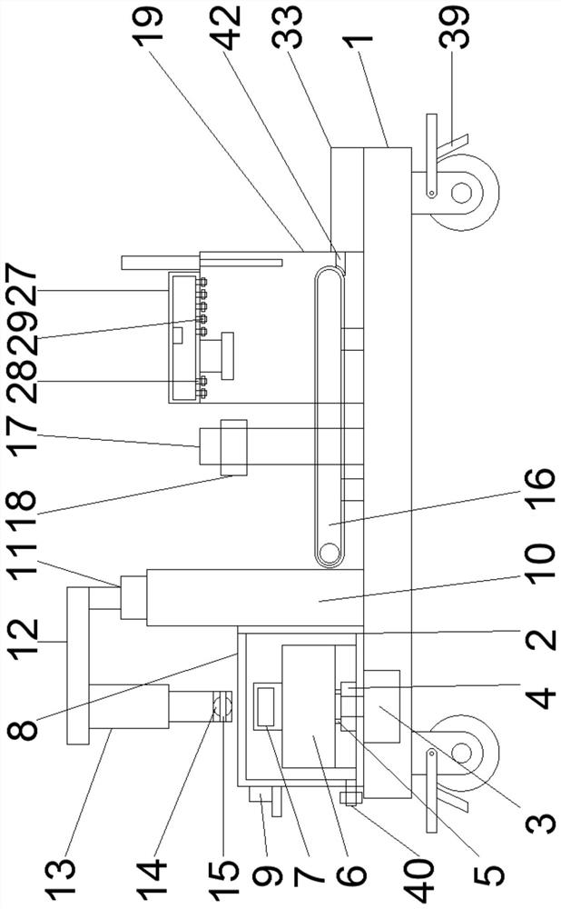
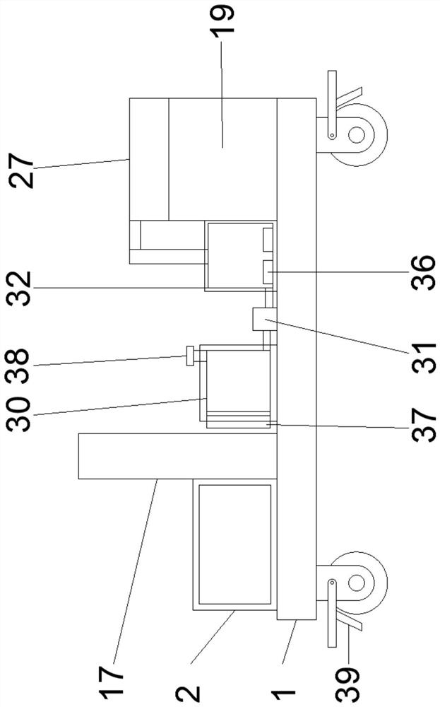
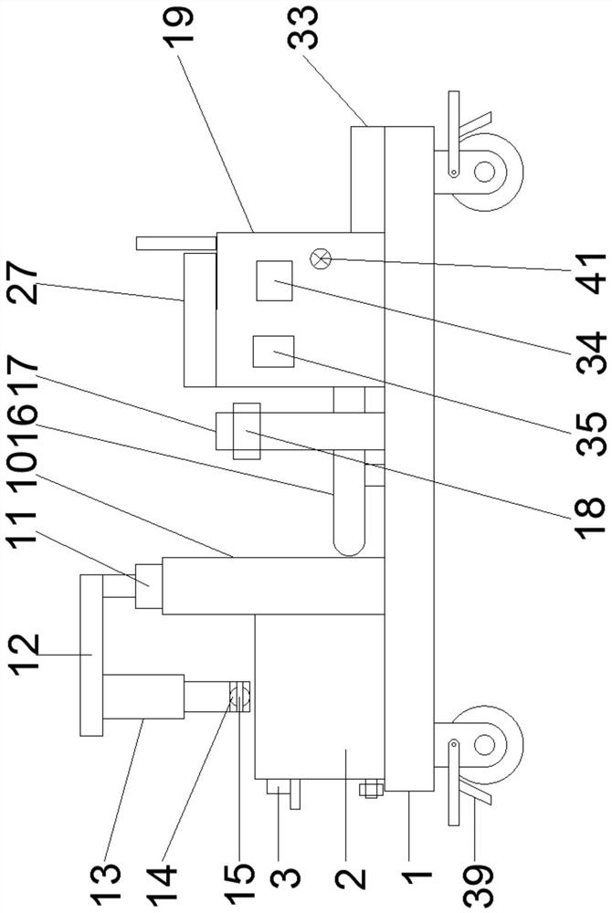
[0023] see Figure 1-8According to the present invention, it includes a base 1, a cleaning box 2 is fixed on one side of the upper end of the base 1, a first positive and negative motor 3 is fixedly embedded at one end of the base 1, and the rotating shaft of the first positive and negative motor 3 extends into the cleaning box 2, one end of the rotating shaft of the first positive and negative motor 3 is fixed with a circular plate 4, and the upper end of the circular plate 4 is symmetrically fixed with a limit rod 5, and the upper end of the circular plate 4 is fixed with the The cleaning frame 6 that matches the circular plate 4, the lower end of the cleaning frame 6 is provided with a first groove that matches the circular plate 4, and the bottom of the first groove is provided with a groove that matches the limit rod 5. Matching second groove, the upper end of the cleaning frame 6 is fixed with a handle 7 through a connecting rod, a box door 8 is hinged on one side of the...
Embodiment 2
[0026] see Figure 1-3 and Figure 8 , for the electric heating block and the fixed plate, the inner wall of the lower end of the heating box 32 is fixed with a number of electric heating blocks 36, and the electric heating blocks 36 are electrically connected with the controller 35, and the first positive and negative The lower end of the motor 3 is fixed with a first fixed plate, one side of the first fixed plate is fixed on one side of the cleaning box 2, and for the universal wheels, the four corners of the lower end of the base 1 are fixed with universal wheels 39 , for the liquid level gauge and the water filling port, a liquid level gauge 37 is embedded on one side of the water tank 30, and a water filling port 38 is opened on the upper side of the water tank 30. For the conveyor belt and the transmission teeth, the cleaning tank 2. A sealing ring is fixed at the connection between the lower end and the rotating shaft of the first reversible motor 3, and a sealing slee...
Embodiment 3
[0029] see figure 1 and image 3 For the sealing ring and the sealing sleeve, the conveyor belt 16 and the transmission teeth 26 are driven by positive and negative motors, and for the drain pipe and the valve, a drain pipe 40 is fixed on one side of the cleaning box 2, so One side of the drainage pipe 40 is fixedly provided with a valve, and for the electromagnetic air release valve, an electromagnetic air release valve 41 is fixedly provided on one side of the sterilizing box 19, and for the sealing plate, one side of the sterilizing box 19 is fixedly provided with a The conveyor belt 16 is fitted with a sealing plate 42 .
[0030] Through the above scheme of the present invention, by arranging the sealing ring, the sealing sleeve, the drain pipe 40, the valve, the electromagnetic air release valve 41 and the sealing plate 42, it is convenient to seal the cleaning box 2 and the disinfection box 19, and it is possible to facilitate the discharge of water in the cleaning box ...
PUM
 Abstract
Description
Claims
Application Information
 - R&D
- Intellectual Property
- Life Sciences
- Materials
- Tech Scout
- Unparalleled Data Quality
- Higher Quality Content
- 60% Fewer Hallucinations
Browse by: Latest US Patents, China's latest patents, Technical Efficacy Thesaurus, Application Domain, Technology Topic, Popular Technical Reports.
© 2025 PatSnap. All rights reserved.Legal|Privacy policy|Modern Slavery Act Transparency Statement|Sitemap|About US| Contact US: help@patsnap.com


