Rapid catalysis device for production of petrochemical industry and working method thereof

A petrochemical and catalytic device technology, applied in the petroleum industry, chemical instruments and methods, catalytic cracking, etc., can solve the problems of frequent cleaning, reduce catalytic cost, slow catalytic, etc., to speed up catalytic speed, reduce catalytic cost, catalytic Process detailed effects

Active Publication Date: 2021-06-11
SHANGHAI PINGWEI TECH DEV CO LTD
View PDF6 Cites 5 Cited by
  • Summary
  • Abstract
  • Description
  • Claims
  • Application Information

AI Technical Summary

Problems solved by technology

[0008] 1. After the oil is brought out from the groove, it is easy to cause dirt, which is not conducive to the cleaning of the device, and requires frequent cleaning
[0009] 2. There are many catalytic steps and the process is complicated, which is not conducive to improving the catalytic efficiency
[0010] 3. There are many impurities inside the oil, and the design of the mixing mechanism is too simple, which is not conducive to improving the mixing efficiency and the catalysis is slow
[0011] 4. There are many driving sources, and the device consumes more electricity, which is not conducive to reducing the cost of catalysis

Method used


Image

  • Rapid catalysis device for production of petrochemical industry and working method thereof
  • Rapid catalysis device for production of petrochemical industry and working method thereof
  • Rapid catalysis device for production of petrochemical industry and working method thereof

Examples


Embodiment Construction

[0053] The technical solutions of the present invention will be further described below in conjunction with the accompanying drawings and through specific implementation methods.

[0054] Wherein, the accompanying drawings are only for illustrative purposes, showing only schematic diagrams, rather than physical drawings, and should not be construed as limitations on this patent; in order to better illustrate the embodiments of the present invention, some parts of the accompanying drawings will be omitted, Enlarged or reduced, does not represent actual product size.

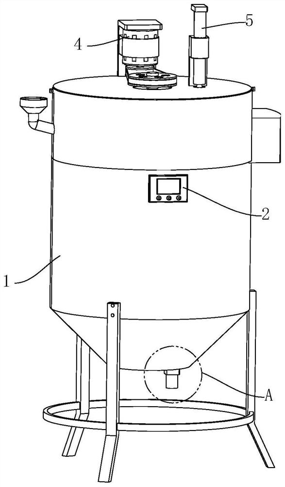
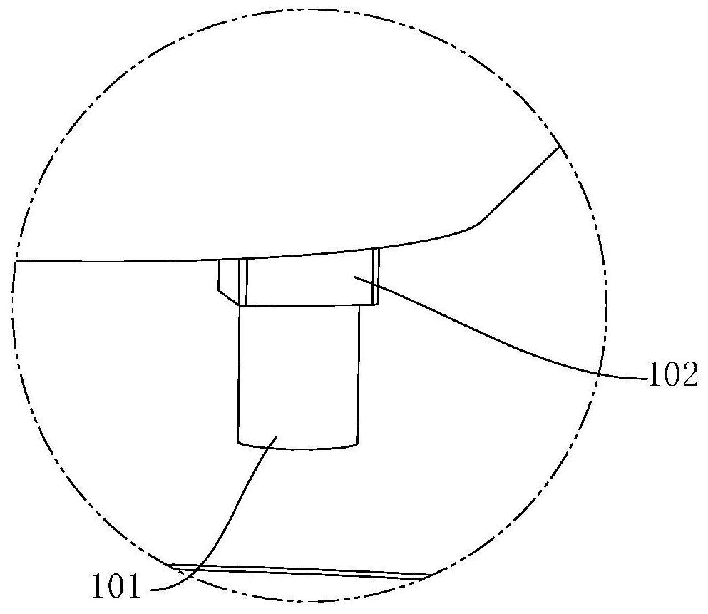
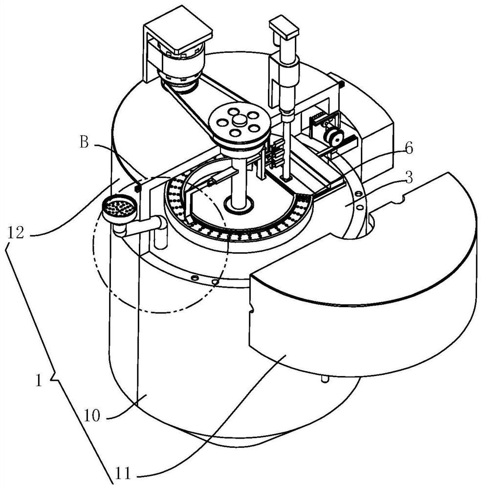
[0055] refer to Figure 1 to Figure 9 A quick catalytic device for petrochemical production as shown, including a reactor 1, the bottom of the reactor 1 is a funnel structure, and also includes a controller 2, a sealing plate 3, a stirring mechanism 4, a catalytic mechanism 5 and a cleaning mechanism 6 , the controller 2 is fixed on the outer wall of the reactor 1, the sealing plate 3 is fixed on the inner top of...


PUM


Abstract

The invention relates to the technical field of petroleum processing, in particular to a rapid catalysis device for production of the petrochemical industry and a working method thereof. The rapid catalysis device comprises a reaction kettle and further comprises a controller, a sealing disc, a stirring mechanism, a catalysis mechanism and a cleaning mechanism, wherein the stirring mechanism comprises a rotating shaft, a driving assembly and three rotating assemblies; the catalysis mechanism comprises a placement frame, a telescopic assembly and a leakage prevention assembly; the cleaning mechanism comprises an arc-shaped collection box, a hammering assembly and a brushing assembly; the arc-shaped collection box is fixedly arranged at the top of the sealing disc; a touch assembly and the brushing assembly are symmetrically arranged on the circumferential outer wall of the rotating shaft; and the driving assembly and the telescopic assembly are electrically connected with the controller. According to the rapid catalysis device for the production of the petrochemical industry and the working method thereof, frequent cleaning is not needed, oil stains are convenient to clean, stirring is more careful, a catalysis process can be accelerated, catalysis efficiency is higher, power consumption is small, and catalysis cost can be reduced.

Description

technical field [0001] The invention relates to the technical field of petroleum processing, in particular to a fast catalytic device for petrochemical production and a working method. Background technique [0002] Catalytic cracking is one of the petroleum refining processes. It is a process in which heavy oil undergoes a cracking reaction under the action of heat and a catalyst, and is converted into cracked gas, gasoline and diesel oil. [0003] In the process of cracking petroleum under the action of a catalyst, some substances inside the petroleum will be adsorbed on the surface of the catalyst, reducing the contact area between the catalyst and petroleum, thereby reducing the catalytic efficiency, and the catalyst is placed inside the petroleum, which is inconvenient to clean; in view of this, The invention provides a catalytic cracking unit for petrochemical production, which has the following characteristics: [0004] (1) A catalytic cracking device for petrochemi...

Claims


Application Information

Patent Timeline
Patent Type & Authority Applications(China)
IPC IPC(8): B01J19/18B01J8/00B01J8/08C10G11/00
CPCB01J19/18B01J8/001B01J8/08C10G11/00
Inventor 袁福德
Owner SHANGHAI PINGWEI TECH DEV CO LTD
Why Eureka
Try Eureka