Pushing mechanism for laser marking device

A push mechanism and laser marking technology, applied in the field of laser marking machines, can solve the problems of untimely retraction and extension of lifting blocks, damage to parts and equipment, and low feeding efficiency, so as to reduce waiting time and improve processing. Efficiency, simple structure effect

Active Publication Date: 2021-06-11
NINGBO BEILONG PRECISION MOLDING
View PDF5 Cites 0 Cited by
  • Summary
  • Abstract
  • Description
  • Claims
  • Application Information

AI Technical Summary

Problems solved by technology

[0004] In order to overcome the problem that the loading and unloading of the laser marking machine in the prior art is generally carried out manually, there are problems of low feeding efficiency and high labor cost, the present invention provides a pushing mechanism for the laser marking device, which can realize automation The loading and unloading conveying function can also solve the problem of damage to parts and equipment caused by the untimely retraction and extension of the lifting block when the control timing of the pushing mechanism is chaotic.

Method used


Image

  • Pushing mechanism for laser marking device
  • Pushing mechanism for laser marking device
  • Pushing mechanism for laser marking device

Examples


Embodiment 1

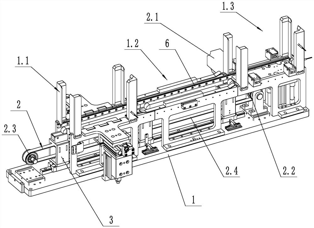
[0023] like figure 1 As shown, a push mechanism for a laser marking device includes a support frame 1, a push drive mechanism 2, a push assembly 3 and a tray, and the support frame 1 includes a loading station 1.1, a processing station 1.2 and an unloading station 1.3, the push assembly 3 and the support frame 1 are slidingly connected through the guide rail slider structure, and the push drive mechanism 2 includes the drive motor 2.1, the driving pulley 2.2, the driven pulley 2.3 and the timing belt 2.4, the driving pulley 2.2 and the driven pulley 2.3 is rotationally connected with the support frame 1, the driving motor 2.1 is fixed with the support frame 1, the driving pulley 2.2 is connected with the output shaft of the driving motor 2.1, and the timing belt 2.4 is arranged on the driving pulley 2.2 and the driven pulley 2.3; the push assembly 3 It is fixed with the synchronous belt 2.4; the upper end of the pushing component 3 is in contact with the side wall of the palle...

Embodiment 2

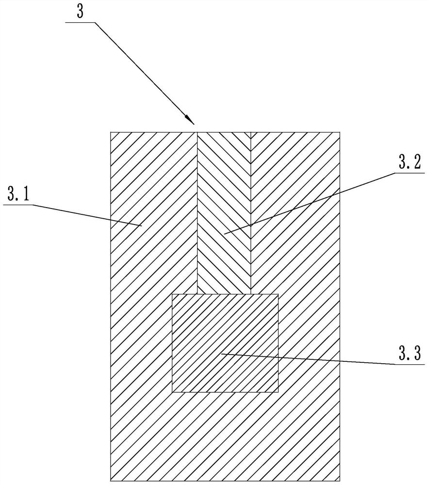
[0026] like figure 2 As shown, the push assembly 3 includes a sliding fixed block 3.1, a lifting block 3.2 and a lifting drive member 3.3, the lifting block 3.2 is slidably connected with the sliding fixed block 3.1 in the vertical direction, the lifting drive member 3.3 is fixed with the sliding fixed block 3.1, and the lifting The telescopic end of the driver 3.3 is connected with the lifting block 3.2. The lifting drive member 3.3 may be a linear drive mechanism such as an air cylinder or an oil cylinder. By implementing the above technical scheme, the lifting block 3.2 can be stretched out or retracted as required, and when the lifting block 3.2 is retracted, the lifting block 3.2 is prevented from contacting the upper pallet, even if there are The tray and the push assembly 3 can also be retracted, thereby reducing waiting time and improving processing efficiency.

Embodiment 3

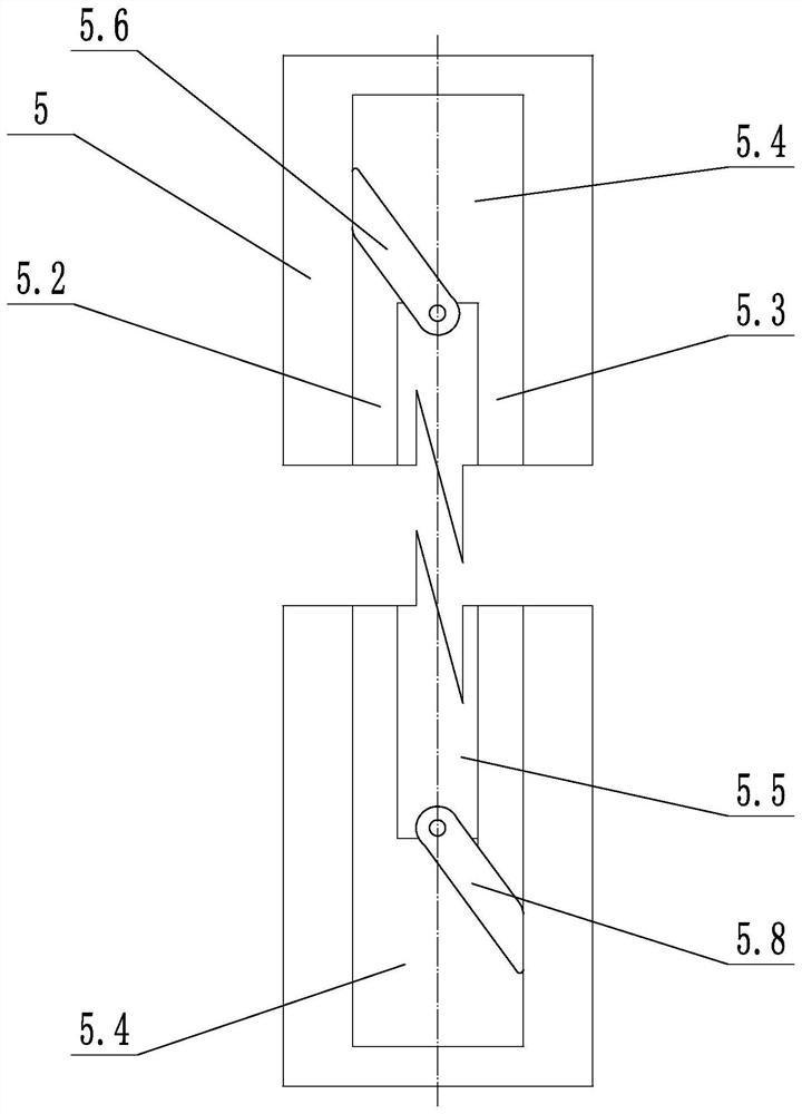
[0028] like image 3 and Figure 4 As shown, the number of the pushing assemblies 3 is two, and the two pushing assemblies 3 are arranged at intervals of one station. The two push assemblies 3 are connected with the same push drive mechanism 2 . The pushing assembly 3 includes a sliding and fixing block 3.1, a lifting block 3.2 and a traverse block 3.4, the sliding and fixing block 3.1 is fixed with the push drive mechanism 2, the sliding and fixing block 3.1 is slidably connected with the support frame 1, and the upper end of the lifting and lowering block 3.2 is connected with the tray. The side walls are in contact, the lifting block 3.2 is slidably connected with the sliding fixed block 3.1 in the vertical direction, the traverse block 3.4 is slidably connected with the sliding fixed block 3.1 in the horizontal direction, and the lifting block 3.2 is provided with a third spring 3.8, the third spring 3.8 One end is connected with the sliding fixed block 3.1, and the othe...


PUM


Abstract

The invention discloses a pushing mechanism for a laser marking device. The pushing mechanism comprises a supporting frame, a pushing driving mechanism, a pushing assembly and a supporting plate; the pushing assembly comprises a sliding fixing block, a lifting block and a transverse moving block, the lifting block is in sliding connection with the sliding fixing block, the transverse moving block is in sliding connection with the sliding fixing block, a first inclined face is arranged on the lifting block, and a second inclined face is arranged on the transverse moving block; a guide plate is arranged on the supporting frame, a first guide long groove, a partition plate, a second guide long groove, a first shifting rod, a first spring, a second shifting rod and a second spring are arranged on the guide plate side by side, and the two ends of the first guide long groove communicate with the two ends of the second guide long groove through communicating grooves; and a shifting block is arranged below the transverse moving block, and the shifting block and the transverse moving block are fixed. According to the pushing mechanism for the laser marking device, the automatic feeding and discharging conveying function can be achieved, and meanwhile, the problem that parts and equipment are damaged due to the fact that the lifting block retracts and stretches out unduly can be solved.

Description

technical field [0001] The invention relates to the technical field of laser marking machines, in particular to a pushing mechanism for a laser marking device. Background technique [0002] The loading and unloading of existing laser marking machines is generally carried out manually. The trays with products are placed on the conveyor line in turn, and transported to the bottom of the laser marking machine through the conveyor line for marking. However, the manual feeding method has the problems of low feeding efficiency and high labor cost. Therefore, the present application designs a pushing mechanism for a laser marking device, which can realize the function of automatically pushing materials during the automatic feeding process. [0003] Chinese Patent Application Publication No. CN207658787U, published on July 27, 2018, titled "An Automatic Feeding Mechanism for a Roll-in and Unwinder", discloses an automatic feeding mechanism for a Roll-in and Unwinder, the roll The ...

Claims


Application Information

Patent Timeline
Patent Type & Authority Applications(China)
IPC IPC(8): B23K26/362B23K26/70
CPCB23K26/362B23K26/70B23K26/702
Inventor 丁济松
Owner NINGBO BEILONG PRECISION MOLDING
Why Eureka
Try Eureka