Reinforcing steel bar machining equipment for reinforced concrete drainage pipe

A reinforced concrete and steel bar processing technology, applied in the field of construction equipment, can solve problems such as steel bar displacement and cutting, and achieve the effect of increasing frictional resistance

Inactive Publication Date: 2021-06-15
李良生
View PDF0 Cites 0 Cited by
  • Summary
  • Abstract
  • Description
  • Claims
  • Application Information

AI Technical Summary

Problems solved by technology

[0003] When using a cutting machine to cut the steel bars used in reinforced concrete drainage pipes, because the cutting machine is to cut the steel bars under the action of external force, the steel bars are cut off due to the large external force. There is a strong throwing out, and because it is cut by strong pressure, it is easy to cause the steel bar to be displaced and cut in the process of contacting the steel bar

Method used


Image

  • Reinforcing steel bar machining equipment for reinforced concrete drainage pipe
  • Reinforcing steel bar machining equipment for reinforced concrete drainage pipe
  • Reinforcing steel bar machining equipment for reinforced concrete drainage pipe

Examples


no. 1 example

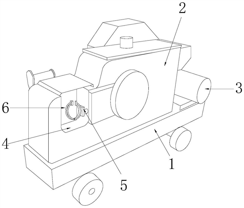
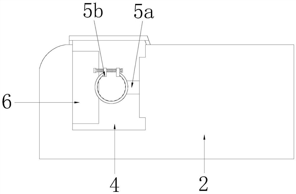
[0029] like Figure 1-Figure 4 As shown, the present invention provides a technical scheme of reinforced concrete drainage pipe reinforcement processing equipment:

[0030] like Figure 1-Figure 3 As shown, a reinforced concrete drainage pipe reinforcement processing equipment, its structure includes a mobile frame 1, equipment main body 2, drive motor 3, processing tank 4, protective device 5, cutting piece 6, the equipment main body 2 is installed on the mobile frame 1 On the upper surface, the driving motor 3 is located on the right side of the equipment main body 2 and cooperates, the processing tank 4 is located on the left side of the equipment main body 2 and is an integrated structure, and the protection device 5 is located on the right side of the processing tank 4 and Located on the front side, the cutting member 6 is installed on the left side inside the processing tank 4, the protection device 5 includes a spring pushing structure 5a and a fastening mechanism 5b, ...

no. 2 example

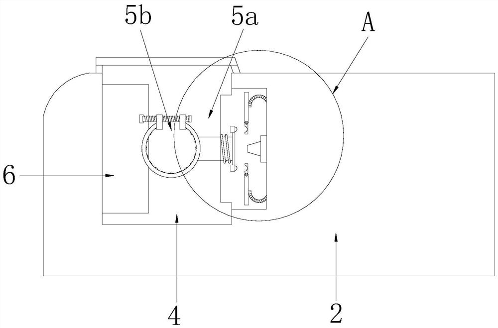
[0039] like Figure 4-Figure 6 As shown, the present invention provides a technical scheme of reinforced concrete drainage pipe reinforcement processing equipment:

[0040] like Figure 4-Figure 5 As shown, a reinforced concrete drainage pipe reinforcement processing equipment, its structure includes the fastening mechanism 5b including arc sleeve 5b1, matching torsion bar 5b2, perforated plate 5b3, screw rod 5b4, connecting rod 5b5, return spring 5b6, limit plate 5b7, there are two arc sleeves 5b1 and they are respectively connected by matching torsion bars 5b2; There are two perforated plates 5b3, the connecting rod 5b5 is installed on the right surface of the arc sleeve 5b1 provided on the right side, and extends into the cavity 5a1, and the return spring 5b6 is nested with the end of the connecting rod 5b5 and is located inside the cavity 5a1, the limiting plate 5b7 is installed on the right end of the connecting rod 5b5, and cooperates with the buckle groove plate 5a24,...


PUM


Abstract

The invention discloses reinforcing steel bar machining equipment for a reinforced concrete drainage pipe. The reinforcing steel bar machining equipment structurally comprises a moving frame, an equipment body, a driving motor, a machining groove, a protection device and a cutting part. The reinforcing steel bar machining equipment has the beneficial effects that through cooperation of an elastic pushing structure and a buckling mechanism, in the reinforcing steel bar cutting-off process, the effect of stable movement is achieved in the contact process through the same-polarity magnetic repulsion effect of buckling pushing parts and magnetic buckling blocks which are arranged in a matched manner, and the reinforcing steel bar is prevented from deviating in the cutting-off process. According to the reinforcing steel bar machining equipment, by the buckling mechanism, the attaching size of an arc sleeve and a reinforcing steel bar is adjusted according to the diameter of the reinforcing steel bar, so that the reinforcing steel bar is clamped and fixed; and meanwhile, inclined strips arranged in the arc sleeve are matched, so that the friction resistance of contact between the reinforcing steel bar and the arc sleeve is increased, and the situation that the cut reinforcing steel bar falls off due to strong pushing force is prevented.

Description

technical field [0001] The invention relates to the field of building construction equipment, more precisely, it relates to a reinforced concrete drainage pipe reinforcement processing equipment. Background technique [0002] In the construction process of municipal water supply and drainage, reinforced concrete water pipes are indispensable. In the process of making reinforced concrete, steel bars are needed. Because the sizes of water pipes are different and the required shapes are also different, the need for steel bars The length is also different, so the steel bars need to be cut and processed. [0003] When using a cutting machine to cut the steel bars used in reinforced concrete drainage pipes, because the cutting machine is to cut the steel bars under the action of external force, the steel bars are cut off due to the large external force. There is a strong throwing out, and because it is cut by strong pressure, it is easy to cause displacement and cutting of the st...

Claims


Application Information

Patent Timeline
Patent Type & Authority Applications(China)
IPC IPC(8): B21F11/00
CPCB21F11/00
Inventor 王炳川
Owner 李良生
Why Eureka
Try Eureka