Filler wire static shaft shoulder friction stir welding and additive manufacturing device and method

A technology of additive manufacturing and friction stir, applied in welding equipment, manufacturing tools, additive processing, etc., can solve the problems of unfavorable additive efficiency and additive accuracy, low efficiency of additive manufacturing, and affecting the performance of additive parts. Achieve the effect of being conducive to technology upgrading and equipment replacement, easy and rapid industrial application, and improving utilization rate

Pending Publication Date: 2021-06-15
SHANDONG UNIV
View PDF7 Cites 20 Cited by
  • Summary
  • Abstract
  • Description
  • Claims
  • Application Information

AI Technical Summary

Problems solved by technology

The inventors found that the friction stir additive manufacturing technology using plates as the feeding mode has three disadvantages: first, the utilization rate of materials is low, and after the completion of the material addition, corresponding material reduction processing needs to be carried out according to the requirements of the molded parts; second, the material addition components It has obvious layering characteristics, and the combination of the interface between the two plates determines the performance of the additive part. When adding materials with the plate as the feed material, it is easy to form interface bonding defects such as unbonded and weak connections, resulting in low interface bonding strength. , affecting the performance of the additive parts; thirdly, the efficiency of additive manufacturing is low, and the feed plate needs to be re-clamped and positioned before each additive, which is not conducive to the efficiency and accuracy of additive materials

Method used


Image

  • Filler wire static shaft shoulder friction stir welding and additive manufacturing device and method
  • Filler wire static shaft shoulder friction stir welding and additive manufacturing device and method
  • Filler wire static shaft shoulder friction stir welding and additive manufacturing device and method

Examples


Embodiment 1

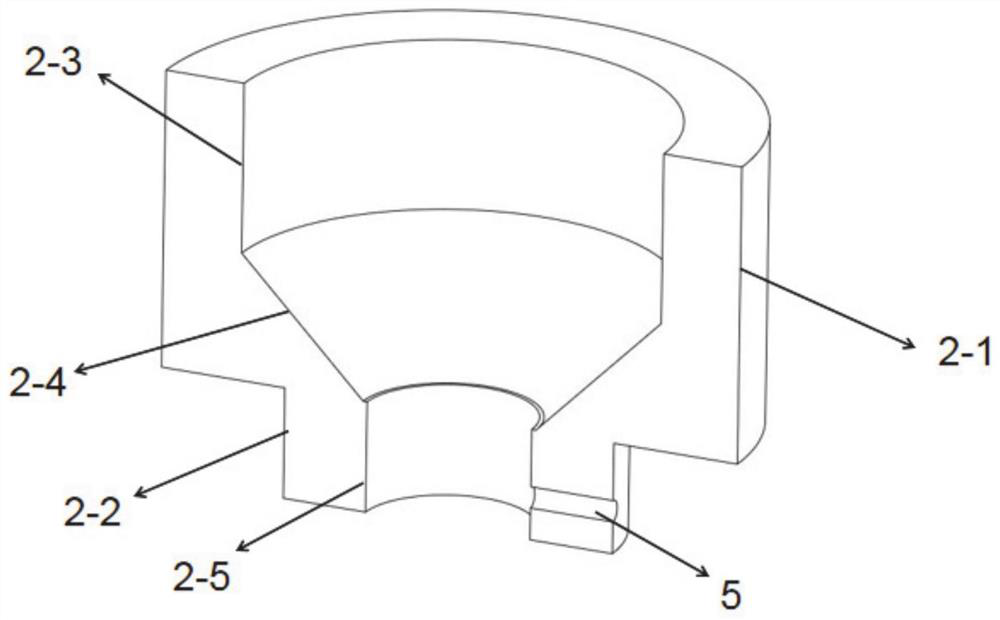
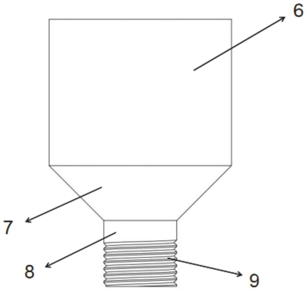
[0044] In a typical implementation of the present application, a static shoulder friction stir welding and additive manufacturing device for filling wire, such as Figure 1-2 As shown, it includes a stirring head 1 and a static shoulder 2 sleeved on the outer periphery of the stirring head. The stirring head is connected to the main shaft of the friction welding machine, and the static shoulder is connected to the three-axis linkage mechanism of the friction welding machine. There is friction stir welding equipment for large-scale transformation, which is conducive to technology upgrading and equipment replacement, and is easy for rapid industrial application.

[0045] The middle position of the static shaft shoulder is provided with a through hole, and the static shaft shoulder is sleeved on the outer periphery of the stirring head through the through hole, and cooperates with the stirring head in a gap, so that the stirring head and the static shaft shoulder are configured to...

Embodiment 2

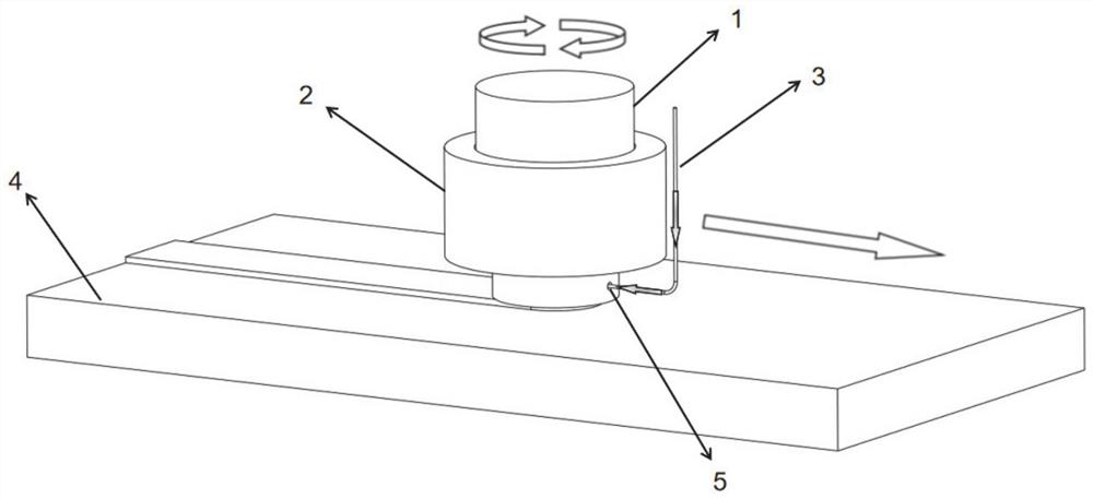
[0057] This embodiment discloses an additive manufacturing method for the static shoulder friction stir welding and additive manufacturing device described in Embodiment 1, such as Figure 3-4 shown, including the following steps:

[0058] Step 1: Insert the stirring head into the static shaft shoulder, and connect the wire to the wire feeding mechanism;

[0059] Step 2: During additive manufacturing, the stirring needle is rotated and inserted into the matrix 4, the rotation direction of the stirring needle is opposite to that of the thread groove, and the matrix is ​​plastically deformed under the action of the stirring needle to form a stirring zone;

[0060] Step 3: Put the wire material into the wire feeding hole, the wire material passes through the wire feeding hole under the thrust of the wire feeding mechanism, and its end contacts the thread groove of the stirring needle, and thermal plasticization occurs under the action of friction , and then the filament in the t...

Embodiment 3

[0078] This embodiment discloses a method for friction stir welding of a static shaft shoulder filled with wire and friction welding of an additive manufacturing device described in Embodiment 1, including the following steps:

[0079] Step 1: Insert the stirring head into the static shaft shoulder, connect the wire material to the wire feeding mechanism, put the wire material into the wire feeding hole, and make contact with the stirring needle;

[0080]Step 2: During welding, the stirring needle is rotated and inserted into the two workpieces to be welded. The rotation direction of the stirring needle is opposite to that of the thread groove, and the material near the joint surface of the workpiece undergoes plastic deformation under the stirring action of the stirring needle to form a stirring zone;

[0081] Step 3: Under the thrust of the wire feeding mechanism, the wire passes through the wire feeding hole, and its end is in contact with the thread groove of the stirring n...


PUM

PropertyMeasurementUnit
diameteraaaaaaaaaa

Abstract

The invention relates to a filler wire static shaft shoulder friction stir welding and additive manufacturing device and method. The filler wire static shaft shoulder friction stir welding and additive manufacturing device comprises a stirring head, the periphery of the stirring head is sleeved with a static shaft shoulder, the stirring head and the static shaft shoulder are configured to synchronously move along a machining track, and the stirring head can rotate around the axis of the stirring head. A threaded groove is formed in the peripheral face of the machining end of the stirring head, the static shaft shoulder is provided with a wire feeding hole, and the wire feeding hole is used for feeding wires to the space between the part, provided with the threaded groove, of the stirring head and the hole face of a through hole formed in the static shaft shoulder. When the device is used for additive manufacturing, the interface bonding defects are avoided, and the bonding strength is guaranteed. And the mechanical property of additive manufacturing parts is greatly improved.

Description

technical field [0001] The invention relates to the technical field of friction stir welding and additive manufacturing, in particular to a device and method for friction stir welding and additive manufacturing of a static shaft shoulder filled with wire. Background technique [0002] The statements herein merely provide background information related to the present invention and do not necessarily constitute prior art. [0003] Additive Manufacturing (AM), also known as "3D printing", is a technology that accumulates materials from top to bottom to construct solid parts layer by layer, compared to traditional subtractive manufacturing. With the development of advanced manufacturing technology, additive manufacturing is currently a hot research direction in the field of manufacturing. It has risen to the strategy and planning of many countries and has been widely used in aerospace, rail transit, biomedicine and other fields. [0004] At present, the commonly used metal addi...

Claims


Application Information

Patent Timeline
Patent Type & Authority Applications(China)
IPC IPC(8): B23K20/12B23K20/16B23K20/26B33Y10/00
CPCB23K20/122B23K20/16B23K20/26B33Y10/00
Inventor 石磊李阳肖亦辰吕晓辉武传松
Owner SHANDONG UNIV
Why Eureka
Try Eureka