Fault identification method and system based on vibration signal imaging

A vibration signal and fault identification technology, applied in character and pattern recognition, instruments, computer components, etc., can solve the problems of dragging down the computer's data processing efficiency and failure, and achieve feature de-correlation and feature dimensionality reduction processing, The effect of improving computational efficiency

Pending Publication Date: 2021-06-15
浙江中自庆安新能源技术有限公司
View PDF0 Cites 1 Cited by
  • Summary
  • Abstract
  • Description
  • Claims
  • Application Information

AI Technical Summary

Problems solved by technology

These data do not play a beneficial role in analyzing the operating status of equipment, diagnosing equipment failures, etc., but will drag down the efficiency of computer processing data

Method used


Image

  • Fault identification method and system based on vibration signal imaging
  • Fault identification method and system based on vibration signal imaging
  • Fault identification method and system based on vibration signal imaging

Examples


Embodiment Construction

[0063] The present invention will be described in detail below in conjunction with the specific embodiments shown in the accompanying drawings, but these embodiments do not limit the present invention, those of ordinary skill in the art make structural, method, or functional changes based on these embodiments All are included in the scope of protection of the present invention.

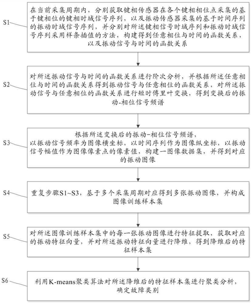
[0064] Such as figure 1 In one embodiment of the present invention shown, the present invention provides a fault identification method based on vibration signal visualization, the method comprising:

[0065] S1. In the current collection period, respectively acquire the key phase time-domain signal sequence based on the key phase collected by the key phase sensor at each key phase point, and the vibration time domain signal sequence based on the time series collected by the vibration sensor, and respectively The time domain sequence of the key phase signal and the vibration time domain signal sequenc...


PUM


Abstract

The invention discloses a fault identification method based on vibration signal imaging, which comprises the following steps: acquiring a key phase time domain signal sequence acquired by a key phase sensor and a vibration time domain signal sequence acquired by a vibration sensor, and constructing a function relationship between any phase and time and a function relationship between a vibration signal and time; performing order analysis on the function relationship between the vibration signal and the time to obtain the function relationship between the vibration signal and any phase, and performing short-time Fourier transform to obtain a transformed vibration-phase signal frequency spectrum; constructing a vibration image along a time sequence by using the transformed vibration-phase signal frequency spectrum, performing feature extraction on a formed image training sample set, and performing dimension reduction on a vibration feature vector to obtain a dimension-reduced feature sample set; and carrying out clustering analysis on the feature sample set after dimension reduction by using a K-means clustering algorithm, and determining a fault category. The vibration data is converted into the image data, lossy compression is carried out, and the data processing speed and efficiency are improved.

Description

technical field [0001] The invention relates to the field of generation and processing of image data, in particular to a fault identification method and system based on vibration signal imaging. Background technique [0002] Vibration exists in various engineering applications such as machinery, vehicles, construction, and aerospace. Engineering structures and equipment generate a large number of vibration signals during the operation process, which contains rich information on the internal characteristics of the structure and equipment operating conditions. It is an important information representation that reflects the state of the system and its changing laws, and directly affects the safe operation of engineering structures and equipment. . [0003] High-frequency vibration signals require a large amount of data to represent, so data compression must be performed on them. However, in the process of compression, higher requirements will be placed on the transmission med...

Claims


Application Information

Patent Timeline
Patent Type & Authority Applications(China)
IPC IPC(8): G06K9/00G06K9/62
CPCG06F2218/08G06F2218/12G06F18/23213G06F18/2135G06F18/214
Inventor 水沛尹旭晔马飞
Owner 浙江中自庆安新能源技术有限公司
Why Eureka
Try Eureka